- 您現(xiàn)在的位置:買賣IC網(wǎng) > PDF目錄98254 > TLV320AIC33IZQE (TEXAS INSTRUMENTS INC) SPECIALTY CONSUMER CIRCUIT, PBGA80 PDF資料下載
參數(shù)資料
| 型號(hào): | TLV320AIC33IZQE |
| 廠商: | TEXAS INSTRUMENTS INC |
| 元件分類: | 消費(fèi)家電 |
| 英文描述: | SPECIALTY CONSUMER CIRCUIT, PBGA80 |
| 封裝: | 5 X 5 MM, ROHS COMPLIANT, PLASTIC, VFBGA-80 |
| 文件頁數(shù): | 49/93頁 |
| 文件大小: | 1427K |
| 代理商: | TLV320AIC33IZQE |
第1頁第2頁第3頁第4頁第5頁第6頁第7頁第8頁第9頁第10頁第11頁第12頁第13頁第14頁第15頁第16頁第17頁第18頁第19頁第20頁第21頁第22頁第23頁第24頁第25頁第26頁第27頁第28頁第29頁第30頁第31頁第32頁第33頁第34頁第35頁第36頁第37頁第38頁第39頁第40頁第41頁第42頁第43頁第44頁第45頁第46頁第47頁第48頁當(dāng)前第49頁第50頁第51頁第52頁第53頁第54頁第55頁第56頁第57頁第58頁第59頁第60頁第61頁第62頁第63頁第64頁第65頁第66頁第67頁第68頁第69頁第70頁第71頁第72頁第73頁第74頁第75頁第76頁第77頁第78頁第79頁第80頁第81頁第82頁第83頁第84頁第85頁第86頁第87頁第88頁第89頁第90頁第91頁第92頁第93頁
www.ti.com ........................................................................................................................................... SLAS480B – JANUARY 2006 – REVISED DECEMBER 2008
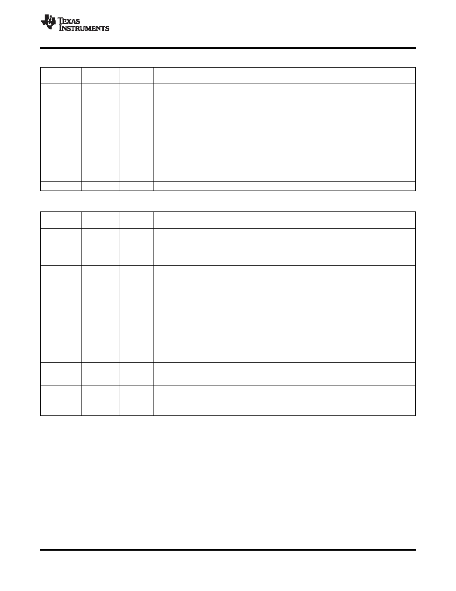
Page 0 / Register 21:
LINE1R to Left ADC Control Register (continued)
BIT
READ/
RESET
DESCRIPTION
WRITE
VALUE
D6–D3
R/W
1111
LINE1R Input Level Control for Left ADC PGA Mix
Setting the input level control to a gain below automatically connects LINE1R to the left ADC
PGA mix
0000: Input level control gain = 0.0-dB
0001: Input level control gain = –1.5-dB
0010: Input level control gain = –3.0-dB
0011: Input level control gain = –4.5-dB
0100: Input level control gain = –6.0-dB
0101: Input level control gain = –7.5-dB
0110: Input level control gain = –9.0-dB
0111: Input level control gain = –10.5-dB
1000: Input level control gain = –12.0-dB
1001–1110: Reserved. Do not write these sequences to these register bits
1111: LINE1R is not connected to the left ADC PGA
D2–D0
R
000
Reserved. Write only zeros to these register bits.
Page 0 / Register 22:
LINE1R to Right ADC Control Register
BIT
READ/
RESET
DESCRIPTION
WRITE
VALUE
D7
R/W
0
LINE1R Single-Ended vs Fully Differential Control
If LINE1R is selected to both left and right ADC channels, both connections must use the same
configuration (single-ended or fully differential mode).
0: LINE1R is configured in single-ended mode
1: LINE1R is configured in fully differential mode
D6–D3
R/W
1111
LINE1R Input Level Control for Right ADC PGA Mix
Setting the input level control to a gain below automatically connects LINE1R to the right ADC
PGA mix
0000: Input level control gain = 0.0-dB
0001: Input level control gain = –1.5-dB
0010: Input level control gain = –3.0-dB
0011: Input level control gain = –4.5-dB
0100: Input level control gain = –6.0-dB
0101: Input level control gain = –7.5-dB
0110: Input level control gain = –9.0-dB
0111: Input level control gain = –10.5-dB
1000: Input level control gain = –12.0-dB
1001–1110: Reserved. Do not write these sequences to these register bits
1111: LINE1R is not connected to the right ADC PGA
D2
R/W
0
Right ADC Channel Power Control
0: Right ADC channel is powered down
1: Right ADC channel is powered up
D1–D0
R/W
00
Right ADC PGA Soft-Stepping Control
00: Right ADC PGA soft-stepping at once per Fs
01: Right ADC PGA soft-stepping at once per two Fs
10-11: Right ADC PGA soft-stepping is disabled
Copyright 2006–2008, Texas Instruments Incorporated
53
Product Folder Link(s): TLV320AIC33
相關(guān)PDF資料 |
PDF描述 |
|---|---|
| TLV320AIC33IRGZT | SPECIALTY CONSUMER CIRCUIT, PQCC48 |
| TLV320AIC33IRGZRG4 | SPECIALTY CONSUMER CIRCUIT, PQCC48 |
| TLV320AIC33IRGZTG4 | SPECIALTY CONSUMER CIRCUIT, PQCC48 |
| TLV320AIC33IRGZ | SPECIALTY CONSUMER CIRCUIT, PQCC48 |
| TLV320AIC36IZQER | SPECIALTY CONSUMER CIRCUIT, PBGA80 |
相關(guān)代理商/技術(shù)參數(shù) |
參數(shù)描述 |
|---|---|
| TLV320AIC33IZQE | 制造商:Texas Instruments 功能描述:AUDIO CODEC IC ((NW)) |
| TLV320AIC33IZQER | 功能描述:接口—CODEC Lo-Pwr Stereo Codec w/6 Inp 7 Otp RoHS:否 制造商:Texas Instruments 類型: 分辨率: 轉(zhuǎn)換速率:48 kSPs 接口類型:I2C ADC 數(shù)量:2 DAC 數(shù)量:4 工作電源電壓:1.8 V, 2.1 V, 2.3 V to 5.5 V 最大工作溫度:+ 85 C 安裝風(fēng)格:SMD/SMT 封裝 / 箱體:DSBGA-81 封裝:Reel |
| TLV320AIC33NIZQE | 制造商:Texas Instruments 功能描述: |
| TLV320AIC33NIZQER | 制造商:Texas Instruments 功能描述: |
| TLV320AIC33RHBRG4 | 制造商:Texas Instruments 功能描述:CODEC - Tape and Reel |
發(fā)布緊急采購,3分鐘左右您將得到回復(fù)。