- 您現(xiàn)在的位置:買賣IC網(wǎng) > PDF目錄378747 > UPD75518 (NEC Corp.) 4 BIT SINGLE-CHIP MICROCOMPUTER PDF資料下載
參數(shù)資料
| 型號: | UPD75518 |
| 廠商: | NEC Corp. |
| 英文描述: | 4 BIT SINGLE-CHIP MICROCOMPUTER |
| 中文描述: | 4位單片機 |
| 文件頁數(shù): | 28/180頁 |
| 文件大小: | 1595K |
| 代理商: | UPD75518 |
第1頁第2頁第3頁第4頁第5頁第6頁第7頁第8頁第9頁第10頁第11頁第12頁第13頁第14頁第15頁第16頁第17頁第18頁第19頁第20頁第21頁第22頁第23頁第24頁第25頁第26頁第27頁當前第28頁第29頁第30頁第31頁第32頁第33頁第34頁第35頁第36頁第37頁第38頁第39頁第40頁第41頁第42頁第43頁第44頁第45頁第46頁第47頁第48頁第49頁第50頁第51頁第52頁第53頁第54頁第55頁第56頁第57頁第58頁第59頁第60頁第61頁第62頁第63頁第64頁第65頁第66頁第67頁第68頁第69頁第70頁第71頁第72頁第73頁第74頁第75頁第76頁第77頁第78頁第79頁第80頁第81頁第82頁第83頁第84頁第85頁第86頁第87頁第88頁第89頁第90頁第91頁第92頁第93頁第94頁第95頁第96頁第97頁第98頁第99頁第100頁第101頁第102頁第103頁第104頁第105頁第106頁第107頁第108頁第109頁第110頁第111頁第112頁第113頁第114頁第115頁第116頁第117頁第118頁第119頁第120頁第121頁第122頁第123頁第124頁第125頁第126頁第127頁第128頁第129頁第130頁第131頁第132頁第133頁第134頁第135頁第136頁第137頁第138頁第139頁第140頁第141頁第142頁第143頁第144頁第145頁第146頁第147頁第148頁第149頁第150頁第151頁第152頁第153頁第154頁第155頁第156頁第157頁第158頁第159頁第160頁第161頁第162頁第163頁第164頁第165頁第166頁第167頁第168頁第169頁第170頁第171頁第172頁第173頁第174頁第175頁第176頁第177頁第178頁第179頁第180頁
28
μ
PD75518(A)
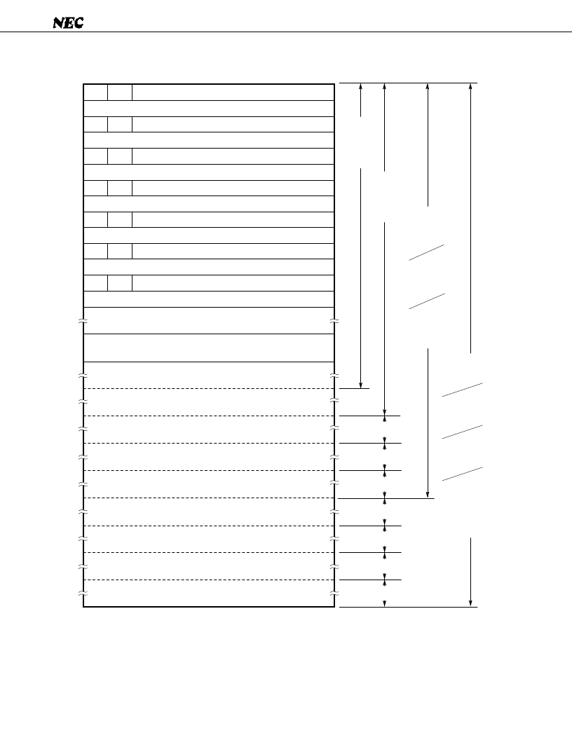
Fig. 3-2 Program Memory Map
Caution The start address of an interrupt vector shown above consists of 14 bits. So, the start address
must be set within a 16K-byte space (0000H to 3FFFH).
Remark
In addition to the above, the BR PCDE and BR PCXA instructions can cause a branch to an address
with only the low-order 8 bits of the PC changed.
MBE
RBE
7
6
0000H
MBE
RBE
0002H
MBE
RBE
0004H
MBE
RBE
0006H
MBE
RBE
0008H
MBE
RBE
000AH
007FH
0080H
0020H
0FFFH
1000H
2FFFH
3000H
5FFFH
6000H
0
Internal reset start address (high-order 6 bits)
Internal reset start address (low-order 8 bits)
INTBT/INT4 start address (high-order 6 bits)
INTBT/INT4 start address (low-order 8 bits)
INT0 start address (high-order 6 bits)
INT0 start address (low-order 8 bits)
INT1 start address (high-order 6 bits)
INT1 start address (low-order 8 bits)
INTCSI0 start address
(high-order 6 bits)
INTCSI0 start address
(low-order 8 bits)
INTT0 start address (high-order 6 bits)
INTT0 start address (low-order 8 bits)
INTTPG start address (high-order 6 bits)
INTTPG start address (low-order 8 bits)
GETI instruction reference table
BR !addr
instruction
branch
address
CALL addr
instruction
branch
address
Branch/call
address specified
in GETI
insturction
CALLF
!faddr
instruction
entry
address
BRCB
!caddr
instruction
branch
address
MBE
RBE
000CH
5000H
4FFFH
4000H
3FFFH
2000H
1FFFH
07FFH
0800H
BR BCDE
BR BCXA
branch address
BRA !addr
instruction
branch address
CALLA !addr
instruction branch
address
BR $addr
instruction
relative
branch address
(–15 to –1,
+2 to +16)
6FFFH
7000H
7F7FH
BRCB !caddr instruction
branch address
BRCB !caddr instruction
branch address
BRCB !caddr instruction
branch address
BRCB !caddr instruction
branch address
BRCB !caddr instruction
branch address
BRCB !caddr instruction
branch address
BRCB !caddr instruction
branch address
相關(guān)PDF資料 |
PDF描述 |
|---|---|
| UPD75518GF | CAT5E PATCH CABLES SNAGLESS, RED 3 FT |
| UPD75518GFA | 4 BIT SINGLE-CHIP MICROCOMPUTER |
| UPD75518A | 4 BIT SINGLE-CHIP MICROCOMPUTER |
| UPD7556 | 4-BIT, SINGLE-CHIP CMOS MICROCOMPUTERS WITH COMPARATOR |
| UPD7566CS | 4-BIT, SINGLE-CHIP CMOS MICROCOMPUTERS WITH COMPARATOR |
相關(guān)代理商/技術(shù)參數(shù) |
參數(shù)描述 |
|---|---|
| UPD7554AG-597-E2 | 制造商:Renesas Electronics Corporation 功能描述: |
| UPD7554AG-597-E2-A | 制造商:Renesas Electronics Corporation 功能描述: |
| UPD7554AG-603-E2 | 制造商:Renesas Electronics Corporation 功能描述: |
| UPD7554AG-603-E2-A | 制造商:Renesas Electronics Corporation 功能描述: |
| UPD7554AG-611-E2 | 制造商:Renesas Electronics Corporation 功能描述: |
發(fā)布緊急采購,3分鐘左右您將得到回復(fù)。