- 您現(xiàn)在的位置:買賣IC網(wǎng) > PDF目錄378747 > UPD75518 (NEC Corp.) 4 BIT SINGLE-CHIP MICROCOMPUTER PDF資料下載
參數(shù)資料
| 型號: | UPD75518 |
| 廠商: | NEC Corp. |
| 英文描述: | 4 BIT SINGLE-CHIP MICROCOMPUTER |
| 中文描述: | 4位單片機 |
| 文件頁數(shù): | 7/180頁 |
| 文件大?。?/td> | 1595K |
| 代理商: | UPD75518 |
第1頁第2頁第3頁第4頁第5頁第6頁當前第7頁第8頁第9頁第10頁第11頁第12頁第13頁第14頁第15頁第16頁第17頁第18頁第19頁第20頁第21頁第22頁第23頁第24頁第25頁第26頁第27頁第28頁第29頁第30頁第31頁第32頁第33頁第34頁第35頁第36頁第37頁第38頁第39頁第40頁第41頁第42頁第43頁第44頁第45頁第46頁第47頁第48頁第49頁第50頁第51頁第52頁第53頁第54頁第55頁第56頁第57頁第58頁第59頁第60頁第61頁第62頁第63頁第64頁第65頁第66頁第67頁第68頁第69頁第70頁第71頁第72頁第73頁第74頁第75頁第76頁第77頁第78頁第79頁第80頁第81頁第82頁第83頁第84頁第85頁第86頁第87頁第88頁第89頁第90頁第91頁第92頁第93頁第94頁第95頁第96頁第97頁第98頁第99頁第100頁第101頁第102頁第103頁第104頁第105頁第106頁第107頁第108頁第109頁第110頁第111頁第112頁第113頁第114頁第115頁第116頁第117頁第118頁第119頁第120頁第121頁第122頁第123頁第124頁第125頁第126頁第127頁第128頁第129頁第130頁第131頁第132頁第133頁第134頁第135頁第136頁第137頁第138頁第139頁第140頁第141頁第142頁第143頁第144頁第145頁第146頁第147頁第148頁第149頁第150頁第151頁第152頁第153頁第154頁第155頁第156頁第157頁第158頁第159頁第160頁第161頁第162頁第163頁第164頁第165頁第166頁第167頁第168頁第169頁第170頁第171頁第172頁第173頁第174頁第175頁第176頁第177頁第178頁第179頁第180頁
7
μ
PD75518(A)
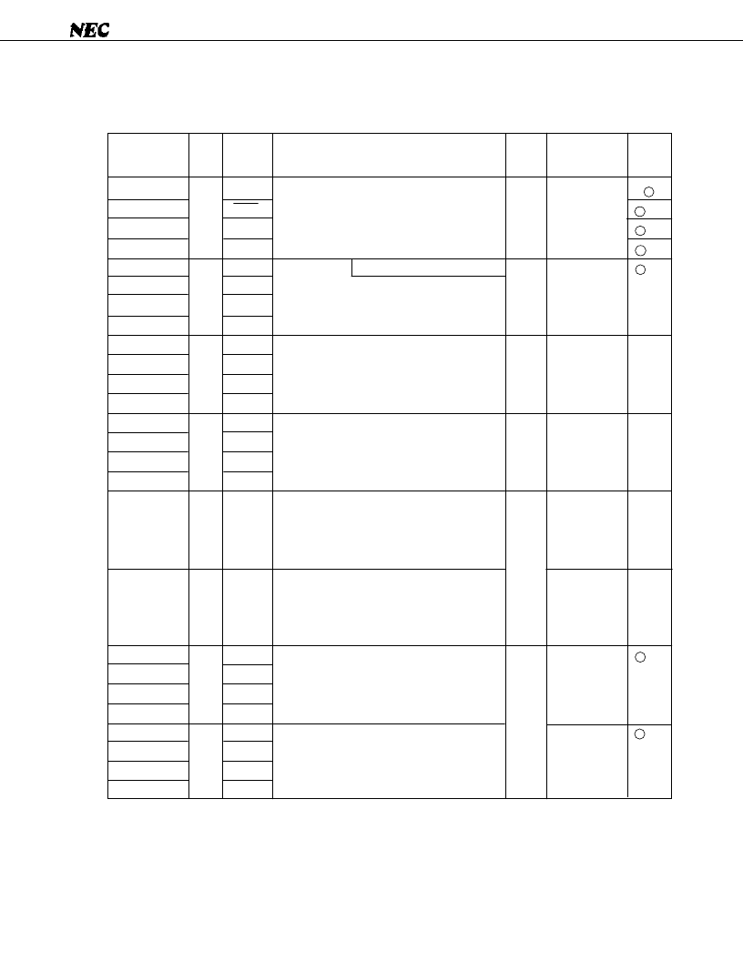
1. PIN FUNCTIONS
1.1 PORT PINS (1/2)
Notes 1.
The circuits enclosed in circles have a Schmitt-triggered input.
2.
An LED can be driven directly.
INT4
SCK0
SO0/SB0
SI0/SB1
INT0
INT1
INT2
TI0
PTO0
–
PCL
BUZ
–
–
–
–
–
–
KR0
KR1
KR2
KR3
KR4
KR5
KR6
KR7
×
×
×
×
H
H
With noise elimination function
4-bit input port (Port 0).
For P01 to P03, pull-up resistors can be
provided by software in units of 3 bits.
4-bit input port (Port 1).
Pull-up resistors can be provided by software
in units of 4 bits.
4-bit I/O port (Port 2).
Pull-up resistors can be provided by software
in units of 4 bits.
Programmable 4-bit I/O port (Port 3).
Input/output can be specified bit by bit.
Pull-up resistors can be provided by software
in units of 4 bits.
N-ch open-drain 4-bit I/O port (Port 4).
A pull-up resistor can be provided bit by bit
(mask option).
Withstand voltage is 10 V in open-drain mode.
N-ch open-drain 4-bit I/O port (Port 5).
A pull-up resistor can be provided bit by bit
(mask option).
Withstand voltage is 10 V in open-drain mode.
Programmable 4-bit I/O port (Port 6).
Input/output can be specified bit by bit.
Pull-up resistors can be provided by software
in units of 4 bits.
4-bit I/O port (Port 7).
Pull-up resistors can be provided by software
in units of 4 bits.
Also
used as
Pin name
I/O
B
F
- A
F
- B
M
- C
B
- C
E - B
E - C
M
M
F
- C
F
- A
8-bit I/O
Input
Input
Input
Input
High level
(when a pull-up
resistor is
provided) or
high impedance
High level
(when a pull-up
resistor is
provided) or
high impedance
Input
Input
When reset
Function
I
I
I/O
I/O
I/O
I/O
I/O
I/O
I/O
Note 1
circuit
type
P00
P01
P02
P03
P10
P11
P12
P13
P20
P21
P22
P23
P30
Note 2
P31
Note 2
P32
Note 2
P33
Note 2
P40-P43
Note 2
P50-P53
Note 2
P60
P61
P62
P63
P70
P71
P72
P73
相關PDF資料 |
PDF描述 |
|---|---|
| UPD75518GF | CAT5E PATCH CABLES SNAGLESS, RED 3 FT |
| UPD75518GFA | 4 BIT SINGLE-CHIP MICROCOMPUTER |
| UPD75518A | 4 BIT SINGLE-CHIP MICROCOMPUTER |
| UPD7556 | 4-BIT, SINGLE-CHIP CMOS MICROCOMPUTERS WITH COMPARATOR |
| UPD7566CS | 4-BIT, SINGLE-CHIP CMOS MICROCOMPUTERS WITH COMPARATOR |
相關代理商/技術參數(shù) |
參數(shù)描述 |
|---|---|
| UPD7554AG-597-E2 | 制造商:Renesas Electronics Corporation 功能描述: |
| UPD7554AG-597-E2-A | 制造商:Renesas Electronics Corporation 功能描述: |
| UPD7554AG-603-E2 | 制造商:Renesas Electronics Corporation 功能描述: |
| UPD7554AG-603-E2-A | 制造商:Renesas Electronics Corporation 功能描述: |
| UPD7554AG-611-E2 | 制造商:Renesas Electronics Corporation 功能描述: |
發(fā)布緊急采購,3分鐘左右您將得到回復。