- 您現(xiàn)在的位置:買賣IC網(wǎng) > PDF目錄361772 > W230 Clocks and Buffers PDF資料下載
參數(shù)資料
| 型號: | W230 |
| 英文描述: | Clocks and Buffers |
| 中文描述: | 時鐘和緩沖器 |
| 文件頁數(shù): | 4/15頁 |
| 文件大小: | 174K |
| 代理商: | W230 |
W230
Document #: 38-07224 Rev. *A
Page 4 of 15
Spread Spectrum Frequency Timing Generator
The device generates a clock that is frequency modulated in
order to increase the bandwidth that it occupies. By increasing
the bandwidth of the fundamental and its harmonics, the am-
plitudes of the radiated electromagnetic emissions are re-
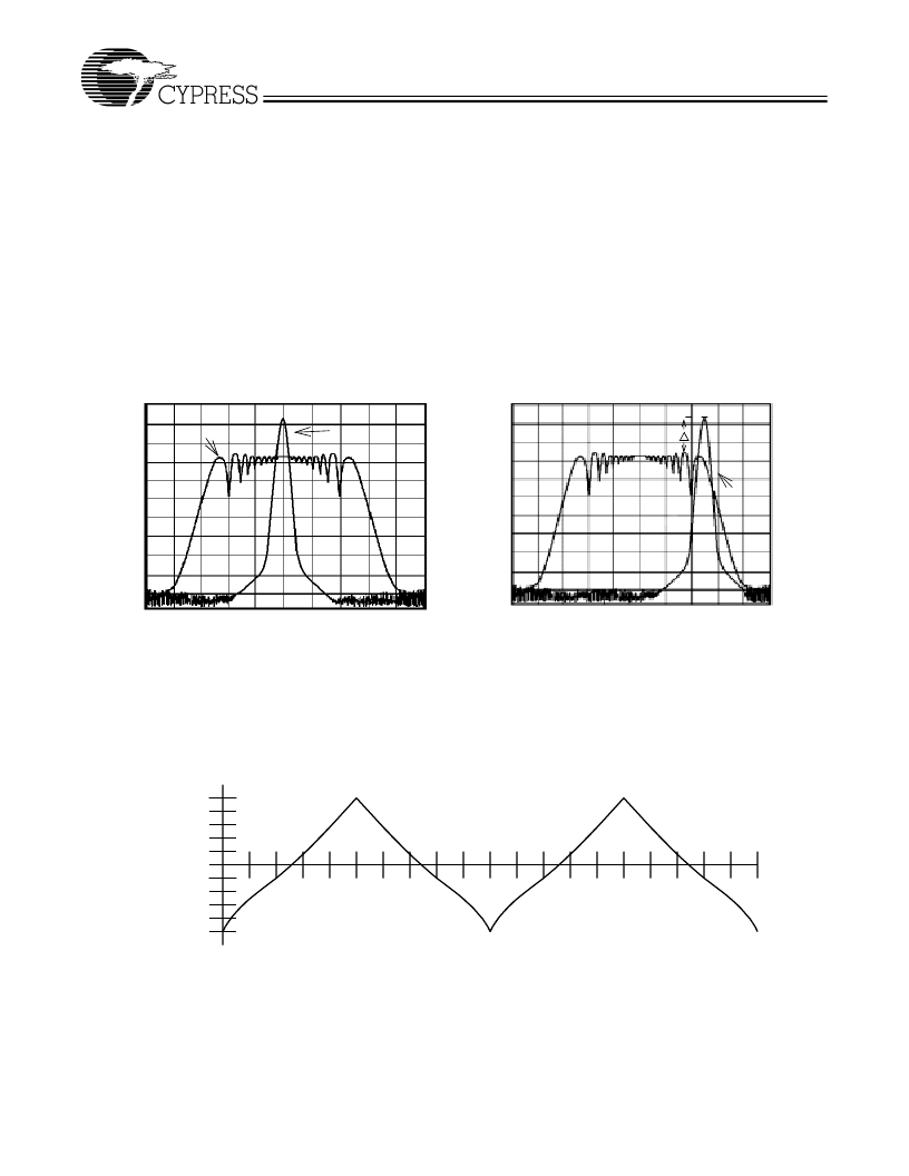
duced. This effect is depicted in
Figure 3
.
As shown in
Figure 3
, a harmonic of a modulated clock has a
much lower amplitude than that of an unmodulated signal. The
reduction in amplitude is dependent on the harmonic number
and the frequency deviation or spread. The equation for the
reduction is:
dB = 6.5 + 9*log
10
(P) + 9*log
10
(F)
Where
P
is the percentage of deviation and
F
is the frequency
in MHz where the reduction is measured.
The output clock is modulated with a waveform depicted in
Figure 4
. This waveform, as discussed in
“
Spread Spectrum
Clock Generation for the Reduction of Radiated Emissions
”
by
Bush, Fessler, and Hardin produces the maximum reduction
in the amplitude of radiated electromagnetic emissions. The
deviation selected for this chip is specified in
Table 6
.
Figure 4
details the Cypress spreading pattern. Cypress does offer op-
tions with more spread and greater EMI reduction. Contact
your local Sales representative for details on these devices.
Spread Spectrum clocking is activated or deactivated by se-
lecting the appropriate values for bits 1
–
0 in data byte 0 of the
I
2
C data stream. Refer to
Table 6
for more details.
Figure 3. Clock Harmonic with and without SSCG Modulation Frequency Domain Representation
SSFTG
Typical Clock
A
Spread
Spectrum
Enabled
EMI Reduction
Non-
Spread
Speactrum
A
Frequency Span (MHz)
Center Spread
Frequency Span (MHz)
Down Spread
Figure 4. Typical Modulation Profile
MAX (0%)
MIN (
–
0.5%)
1
2
3
4
5
6
7
8
9
1
1
2
3
4
5
6
7
8
9
1
F
相關(guān)PDF資料 |
PDF描述 |
|---|---|
| W231024-20 | x8 ROM (Mask Programmable) |
| W231024-30 | x8 ROM (Mask Programmable) |
| W231024H-20 | x8 ROM (Mask Programmable) |
| W231024H-30 | x8 ROM (Mask Programmable) |
| W23128-15 | x8 ROM (Mask Programmable) |
相關(guān)代理商/技術(shù)參數(shù) |
參數(shù)描述 |
|---|---|
| W230-03 | 制造商:CYPRESS 制造商全稱:Cypress Semiconductor 功能描述:Spread Spectrum FTG for VIA K7 Chipset |
| W-2302 | 制造商:MISCELLANEOUS 功能描述: |
| W230CR3.80HR | 制造商:Calmark 功能描述: |
| W230E-1-12 | 功能描述:固態(tài)繼電器-工業(yè)安裝 PC MNT 1.5A 12V/120V RoHS:否 制造商:Crydom 控制電壓范圍:4 VDC to 32 VDC 負載電壓額定值:7 VDC to 72 VDC 負載電流額定值:160 A 觸點形式: 輸出設備:SSR 安裝風格:Panel |
| W230E1-12 | 制造商:未知廠家 制造商全稱:未知廠家 功能描述: |
發(fā)布緊急采購,3分鐘左右您將得到回復。