- 您現(xiàn)在的位置:買賣IC網(wǎng) > PDF目錄361790 > W6692ACD ISDN LINE INTERFACE|BASIC|CMOS|QFP|100PIN|PLASTIC PDF資料下載
參數(shù)資料
| 型號(hào): | W6692ACD |
| 英文描述: | ISDN LINE INTERFACE|BASIC|CMOS|QFP|100PIN|PLASTIC |
| 中文描述: | 綜合業(yè)務(wù)數(shù)字網(wǎng)線接口|基本|的CMOS | QFP封裝| 100引腳|塑料 |
| 文件頁(yè)數(shù): | 45/101頁(yè) |
| 文件大小: | 851K |
| 代理商: | W6692ACD |
第1頁(yè)第2頁(yè)第3頁(yè)第4頁(yè)第5頁(yè)第6頁(yè)第7頁(yè)第8頁(yè)第9頁(yè)第10頁(yè)第11頁(yè)第12頁(yè)第13頁(yè)第14頁(yè)第15頁(yè)第16頁(yè)第17頁(yè)第18頁(yè)第19頁(yè)第20頁(yè)第21頁(yè)第22頁(yè)第23頁(yè)第24頁(yè)第25頁(yè)第26頁(yè)第27頁(yè)第28頁(yè)第29頁(yè)第30頁(yè)第31頁(yè)第32頁(yè)第33頁(yè)第34頁(yè)第35頁(yè)第36頁(yè)第37頁(yè)第38頁(yè)第39頁(yè)第40頁(yè)第41頁(yè)第42頁(yè)第43頁(yè)第44頁(yè)當(dāng)前第45頁(yè)第46頁(yè)第47頁(yè)第48頁(yè)第49頁(yè)第50頁(yè)第51頁(yè)第52頁(yè)第53頁(yè)第54頁(yè)第55頁(yè)第56頁(yè)第57頁(yè)第58頁(yè)第59頁(yè)第60頁(yè)第61頁(yè)第62頁(yè)第63頁(yè)第64頁(yè)第65頁(yè)第66頁(yè)第67頁(yè)第68頁(yè)第69頁(yè)第70頁(yè)第71頁(yè)第72頁(yè)第73頁(yè)第74頁(yè)第75頁(yè)第76頁(yè)第77頁(yè)第78頁(yè)第79頁(yè)第80頁(yè)第81頁(yè)第82頁(yè)第83頁(yè)第84頁(yè)第85頁(yè)第86頁(yè)第87頁(yè)第88頁(yè)第89頁(yè)第90頁(yè)第91頁(yè)第92頁(yè)第93頁(yè)第94頁(yè)第95頁(yè)第96頁(yè)第97頁(yè)第98頁(yè)第99頁(yè)第100頁(yè)第101頁(yè)
W6692A
Publication Release Date: July 2000
- 45 -
Revision A1
There are two interrupt input pins : XINTIN0, XINTIN1. Whenever signal level changes (eith rising or
falling), a maskable interrupt is generated which in turn will make an interrupt request on PCI bus if it
is unmasked. The interrupt status bits are ISTA:XINT0, ISTA:XINT1. The mask bits are IMASK:
XINT0, IMASK:XINT1. In addition, the signal level can be read at bits SQR: XIND0, SQR; XIND1.
These pins can be used for monitor of SLIC hook state and/or DTMF data valid status.
The IO interface can be programmed as simple IO (PCTL: XMODE = 0) or 8-bit microprocessor
interface (PCTL: XMODE = 1). As simple IOs, the pin data are accessed via XADDR and XDATA
registers. The register data is output on the pin if its output enable bit is set, the read data reflects the
current level of pin. In this mode, a maximum of 11 IO ports are supported.
If programmed as 8-bit microprocessor mode, an 8-bit multiplexed bus is used to control peripheral
deveces. The address and data are multiplexed on XAD7-0. XALE is used for address latch and
XRDB, XWRB are used for read/write strobe. To access peripheral device, first write the desired
address in XADDR register and then read/write data at XDATA register. In this mode, a maximum of
256 byte ports can be supported by adding some glue TTLs on board.
8. REGISTER DESCRIPTIONS
Note
: For all the internal registers, only byte access is allowed in all cases.
8.1 Chip Control and D_ch HDLC Controller
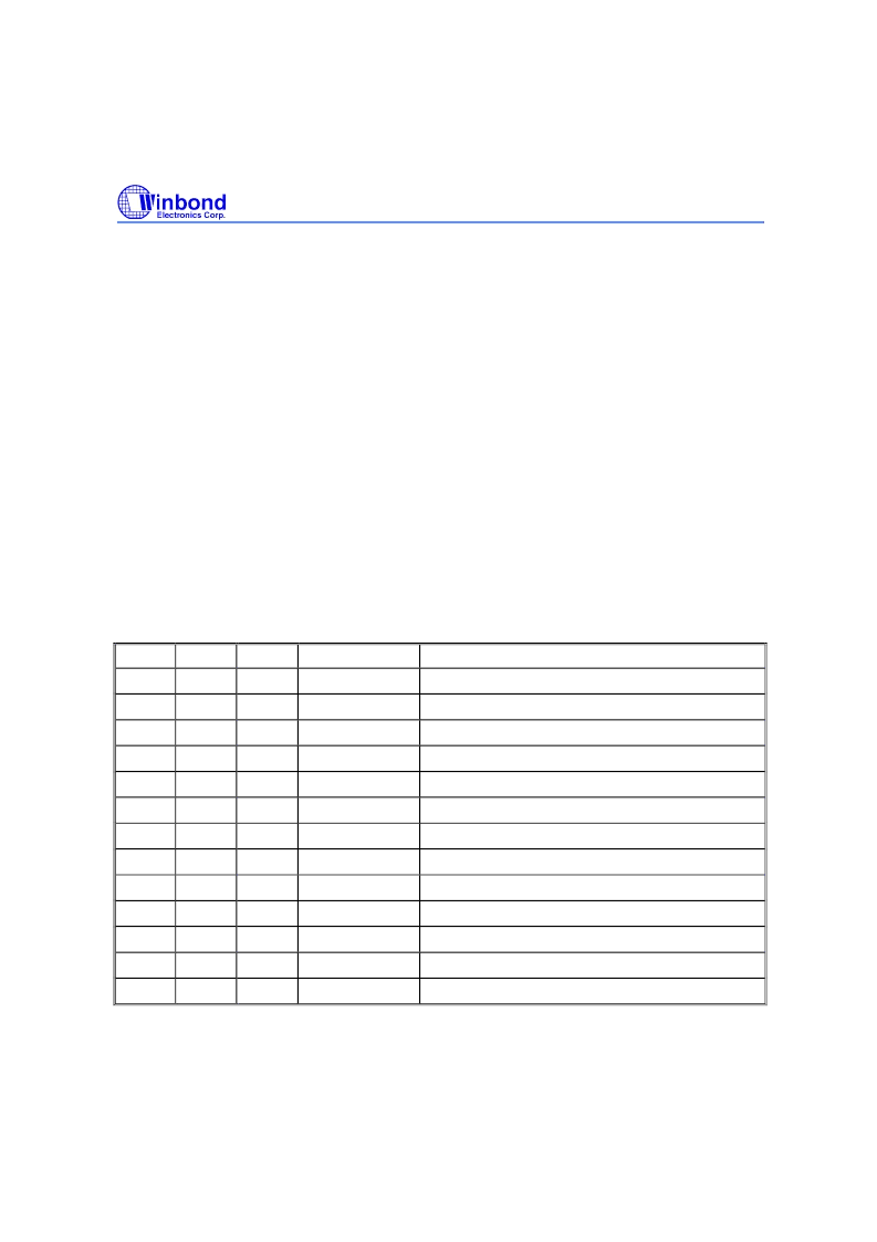
TABLE 8.1 REGISTER ADDRESS MAP: CHIP CONTROL AND D CHANNEL HDLC
Section Offset Access Register Name
8.1.1
00/00
R
Description
D_RFIFO
D channel receive FIFO
8.1.2
04/01
W
D_XFIFO
D channel transmit FIFO
8.1.3
08/02
W
D_CMDR
D channel command register
8.1.4
0C/03
R/W
D_MODE
D channel mode control
8.1.5
10/04
R/W
TIMR1
Timer 1
8.1.6
14/05
R_clear
ISTA
Interrupt status register
8.1.7
18/06
R/W
IMASK
Interrupt mask register
8.1.8
1C/07 R_clear
D_EXIR
D channel extended interrupt
8.1.9
20/08
R/W
D_EXIM
D channel extended interrupt mask
8.1.10
24/09
R
D_XSTA
D channel
transmit
status
8.1.11
28/0A
R
D_RSTA
D channel receive status
8.1.12
2C/0B
R/W
D_SAM
D channel address mask 1
8.1.13
30/0C
R/W
D_SAP1
D channel individual SAPI 1
相關(guān)PDF資料 |
PDF描述 |
|---|---|
| W6692ACF | ISDN LINE INTERFACE|BASIC|CMOS|QFP|100PIN|PLASTIC |
| W6694A | TE Mode S/T Controller with USB 1.1 Interface |
| W6694CD | USB Bus ISDN S/T-Controller |
| W7020 | Telecommunication IC |
| W722 | Controller Miscellaneous - Datasheet Reference |
相關(guān)代理商/技術(shù)參數(shù) |
參數(shù)描述 |
|---|---|
| W6692ACF | 制造商:未知廠家 制造商全稱:未知廠家 功能描述:ISDN LINE INTERFACE|BASIC|CMOS|QFP|100PIN|PLASTIC |
| W6694 | 制造商:WINBOND 制造商全稱:Winbond 功能描述:USB Bus ISDN S/T-Controller |
| W6694A | 制造商:未知廠家 制造商全稱:未知廠家 功能描述:TE Mode S/T Controller with USB 1.1 Interface |
| W6694CD | 制造商:WINBOND 制造商全稱:Winbond 功能描述:USB Bus ISDN S/T-Controller |
| W66ARX-18 | 制造商:Magnecraft 功能描述: |
發(fā)布緊急采購(gòu),3分鐘左右您將得到回復(fù)。