- 您現(xiàn)在的位置:買賣IC網(wǎng) > PDF目錄376462 > XRT8001IP (EXAR CORP) WAN Clock for T1 and E1 Systems PDF資料下載
參數(shù)資料
| 型號: | XRT8001IP |
| 廠商: | EXAR CORP |
| 元件分類: | 時(shí)鐘及定時(shí) |
| 英文描述: | WAN Clock for T1 and E1 Systems |
| 中文描述: | 8001 SERIES, PLL BASED CLOCK DRIVER, 2 TRUE OUTPUT(S), 0 INVERTED OUTPUT(S), PDIP18 |
| 封裝: | 0.300 INCH, PLASTIC, DIP-18 |
| 文件頁數(shù): | 24/48頁 |
| 文件大小: | 1054K |
| 代理商: | XRT8001IP |
第1頁第2頁第3頁第4頁第5頁第6頁第7頁第8頁第9頁第10頁第11頁第12頁第13頁第14頁第15頁第16頁第17頁第18頁第19頁第20頁第21頁第22頁第23頁當(dāng)前第24頁第25頁第26頁第27頁第28頁第29頁第30頁第31頁第32頁第33頁第34頁第35頁第36頁第37頁第38頁第39頁第40頁第41頁第42頁第43頁第44頁第45頁第46頁第47頁第48頁

XRT8001
24
Rev. 1.01
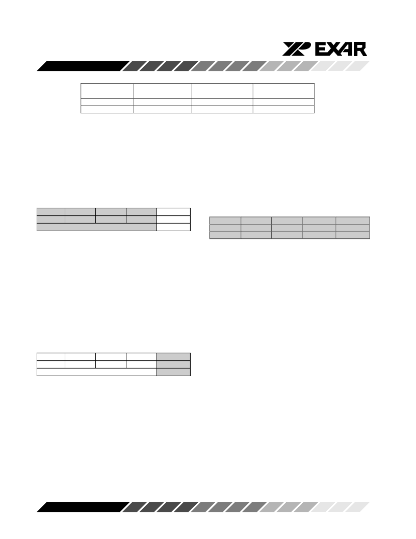
Input
Frequency
56kHz
64kHz
PLL1 Output
Frequency
1.544MHz
1.544MHz
PLL2 Output
Frequency
2.048MHz
2.048MHz
Value to Write to
D4 – D1 in CR0
0011
0111
Table 5. Listing of “Input Frequency” and “Output Frequency”
Cases for “Reverse/Master” Mode Operation
Step 3
– Upon reviewing Table 5, write the listed value
(under the “Value to Write to D4 – D1 in CR0” register)
into the D4 through D1 bit-fields within Command
Register CR0, as illustrated below:
Command Register CR0 (Address = 0x00)
D4
D3
D2
IOC4
IOC3
IOC2
Value to Write to D4 – D1 in CR0
D1
IOC1
D0
PL1EN
X
Note:
If the user wishes to output a clock signal via the
CLK1 output signal, then he/she should also write a “1” into
the “PL1EN” bit-field within Command Register CR0.
This step configures the XRT8001 to operate in the
“Reverse/Master” Mode.
Step 4
– Write a “1” into the “PL2EN” bit-field within
Command Register CR1 (if you wish to output a clock
signal via the “CLK2” output pin), as illustrated below:
Command Register, CR1 (Address = 0x01)
D4
D3
D2
M4
M3
M2
Don’t Care
D1
M1
D0
PL2EN
1
Notes:
1. The value of the “D4 through D1” bit-fields within
Command Register, CR1 are “Don’t Care”.
2. The contents of Command Registers CR2 and
CR3 are “Don’t Care”.
Step 5
– Enable any of the following output signals as
appropriate: SYNC”, CLK1, CLK2 and LOCKDET.
This is accomplished by writing a “1” into the corre-
sponding bit-fields, within Command Register CR4, as
illustrated below:
Command Register CR4, (Address = 0x04)
D4
D3
SYNCEN
CLK1EN
CLK2EN
1
1
D2
D1
D0
LDETDIS2
0
LDETDIS1
0
1
Note:
For information on the “LDETDIS1” and “LDETDIS2”
bit-fields, please see Table 3.
6.2 The “Fractional T1/E1 Reverse/Master” Mode
When the XRT8001 WAN Clock has been configured to
operate in the “Fractional T1/E1 Reverse/Master"
Mode, then it will accept either a “P x 56kHz” or a “P x
64kHz” clock signal via the “FIN” input pin (pin 3). In
response, the XRT8001 will output either a 1.544MHz
or a 2.048MHz clock signal via the CLK1 and/or CLK2
outputs.
A simple illustration of the XRT8001 WAN Clock,
operating in the “Fractional T1/E1 Reverse/Master”
Mode is presented in Figure 15.
相關(guān)PDF資料 |
PDF描述 |
|---|---|
| XRT8010 | 312MHZ CLOCK & CRYSTAL MULTIPLIER WITH LVDS OUTPUTS |
| XRT8010IL | 312MHZ CLOCK & CRYSTAL MULTIPLIER WITH LVDS OUTPUTS |
| XRT8020 | 650 MHZ CLOCK & CRYSTAL MULTIPLIER WITH LVDS OUTPUTS |
| XRT8020IL | 650 MHZ CLOCK & CRYSTAL MULTIPLIER WITH LVDS OUTPUTS |
| XRT81L27IV | SEVEN CHANNEL E1 LINE INTERFACE UNIT WITH CLOCK RECOVERY |
相關(guān)代理商/技術(shù)參數(shù) |
參數(shù)描述 |
|---|---|
| XRT8001IP-F | 功能描述:鎖相環(huán) - PLL RoHS:否 制造商:Silicon Labs 類型:PLL Clock Multiplier 電路數(shù)量:1 最大輸入頻率:710 MHz 最小輸入頻率:0.002 MHz 輸出頻率范圍:0.002 MHz to 808 MHz 電源電壓-最大:3.63 V 電源電壓-最小:1.71 V 最大工作溫度:+ 85 C 最小工作溫度:- 40 C 封裝 / 箱體:QFN-36 封裝:Tray |
| XRT8010 | 制造商:EXAR 制造商全稱:EXAR 功能描述:312MHZ CLOCK & CRYSTAL MULTIPLIER WITH LVDS OUTPUTS |
| XRT8010ES | 功能描述:鎖相環(huán) - PLL RoHS:否 制造商:Silicon Labs 類型:PLL Clock Multiplier 電路數(shù)量:1 最大輸入頻率:710 MHz 最小輸入頻率:0.002 MHz 輸出頻率范圍:0.002 MHz to 808 MHz 電源電壓-最大:3.63 V 電源電壓-最小:1.71 V 最大工作溫度:+ 85 C 最小工作溫度:- 40 C 封裝 / 箱體:QFN-36 封裝:Tray |
| XRT8010IL | 制造商:EXAR 制造商全稱:EXAR 功能描述:312MHZ CLOCK & CRYSTAL MULTIPLIER WITH LVDS OUTPUTS |
| XRT8010IL-F | 功能描述:鎖相環(huán) - PLL . . RoHS:否 制造商:Silicon Labs 類型:PLL Clock Multiplier 電路數(shù)量:1 最大輸入頻率:710 MHz 最小輸入頻率:0.002 MHz 輸出頻率范圍:0.002 MHz to 808 MHz 電源電壓-最大:3.63 V 電源電壓-最小:1.71 V 最大工作溫度:+ 85 C 最小工作溫度:- 40 C 封裝 / 箱體:QFN-36 封裝:Tray |
發(fā)布緊急采購,3分鐘左右您將得到回復(fù)。