- 您現在的位置:買賣IC網 > PDF目錄373891 > AD6636BBCZ1 (Analog Devices, Inc.) 150 MSPS Wideband Digital Down-Converter (DDC) PDF資料下載
參數資料
| 型號: | AD6636BBCZ1 |
| 廠商: | Analog Devices, Inc. |
| 元件分類: | 數字上/下變頻 |
| 英文描述: | 150 MSPS Wideband Digital Down-Converter (DDC) |
| 中文描述: | 150MSPS的寬帶數字下變頻器(DDC) |
| 文件頁數: | 27/72頁 |
| 文件大小: | 1629K |
| 代理商: | AD6636BBCZ1 |
第1頁第2頁第3頁第4頁第5頁第6頁第7頁第8頁第9頁第10頁第11頁第12頁第13頁第14頁第15頁第16頁第17頁第18頁第19頁第20頁第21頁第22頁第23頁第24頁第25頁第26頁當前第27頁第28頁第29頁第30頁第31頁第32頁第33頁第34頁第35頁第36頁第37頁第38頁第39頁第40頁第41頁第42頁第43頁第44頁第45頁第46頁第47頁第48頁第49頁第50頁第51頁第52頁第53頁第54頁第55頁第56頁第57頁第58頁第59頁第60頁第61頁第62頁第63頁第64頁第65頁第66頁第67頁第68頁第69頁第70頁第71頁第72頁
AD6636
Rev. 0 | Page 27 of 72
0
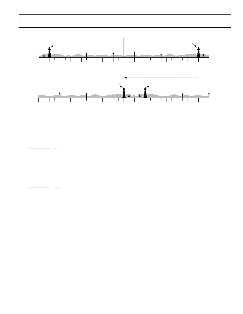
NCO TUNES SIGNAL TO
SIGNAL OF INTEREST
AFTER FREQUENCY TRANSLATION
SIGNAL OF INTEREST
SIGNAL OF INTEREST IMAGE
SIGNAL OF INTEREST IMAGE
–fs/2
–7fs/8
–3fs/8
–5fs/16
–fs/4
–3fs/16
–fs/8
–fs/16
DC
fs/16
fs/8
3fs/16
fs/4
5fs/16
3fs/8
7fs/8
fs/2
–fs/2
–7fs/8
–3fs/8
–5fs/16
–fs/4
–3fs/16
–fs/8
–fs/16
DC
fs/16
fs/8
3fs/16
fs/4
5fs/16
3fs/8
7fs/8
fs/2
FREQUENCY TRANSLATION (SINGLE 1MHz CHANNEL TUNED TO BASEBAND)
WIDEBAND INPUT SPECTRUM (30MHz FROM HIGH SPEED ADC)
WIDEBAND INPUT SPECTRUM (–fsamp/2
TO
fsamp/2)
Figure 30. Frequency Translation Principle Using the NCO and Mixer
For example, if the carrier frequency is 100 MHz and the clock
frequency is 80 MHz,
(
25
.
=
80
clk
f
)
20
=
,
mod
clk
ch
f
f
This, in turn, converts to 0x4000 0000 in the 32-bit twos
complement representation for
NCO_FREQ
.
If the carrier frequency is 50 MHz and the clock frequency is
80 MHz,
(
125
.
=
80
clk
f
)
10
=
,
mod
clk
ch
f
f
This, in turn, converts to 0xE000 0000 in the twos complement
32-bit representation.
Mixer
The NCO is accompanied by a mixer. Its operation is similar to
an analog mixer. It does the down-conversion of input signals
(real or complex) by using the NCO frequency as a local
oscillator. For real input signals, this mixer performs a real
mixer operation (with two multipliers). For complex input
signals, the mixer performs a complex mixer operation (with
four multipliers). The mixer adjusts its operation based on the
input signal (real or complex) provided to each individual
channel.
Bypass
The NCO and the mixer can be bypassed individually in each
channel by writing Logic 1 in the NCO bypass bit in the NCO
control register of the channel under consideration. When
bypassed, down-conversion is not performed and the AD6636
channel functions simply as a real filter on complex data. This is
useful for baseband sampling applications, in which the input
Port A (or C) is connected to the I signal path within the filter
and the Input Port B (or D) is connected to the Q signal path.
This might be desired, if the digitized signal has already been
converted to baseband in prior analog stages or by other digital
preprocessing.
Clear Phase Accumulator on Hop
When clear NCO accumulator bit of NCO control register is set
(Logic 1), the NCO phase accumulator is cleared prior to a
frequency hop. Refer to the Chip Synchronization section for
details on frequency hopping. This ensures a consistent phase of
the NCO on each hop. The NCO phase offset is unaffected by
this setting and is still in effect. If phase-continuous hopping is
needed, this bit should be cleared (NCO accumulator is not
cleared). The last phase in the NCO phase register is the
initiating point for the new frequency.
Phase Dither
The AD6636 provides a phase dither option for improving the
spurious performance of the NCO. Writing Logic 1 in the phase
dither enable bit of NCO control register of individual channels
enables phase dither. When phase dither is enabled, random
phase is added to LSBs of the phase accumulator of the NCO.
When phase dither is enabled, spurs due to phase truncation in
the NCO are randomized.
The energy from these spurs is spread into the noise floor and
the spurious free dynamic range is increased at the expense of a
very slight decrease in the SNR. The choice of whether to use
phase dither in a system is ultimately decided by the system
goals. If lower spurs are desired at the expense of a slightly
raised noise floor, phase dither should be employed. If a low
noise floor is desired and the higher spurs can be tolerated or
filtered by subsequent stages, then phase dither is not needed.
相關PDF資料 |
PDF描述 |
|---|---|
| AD6636BC | 150 MSPS Wideband Digital Down-Converter (DDC) |
| AD6636CBCZ1 | 150 MSPS Wideband Digital Down-Converter (DDC) |
| AD6636PCB | 150 MSPS Wideband Digital Down-Converter (DDC) |
| AD664(中文) | Monolithic 12-Bit Quad DAC(單片12位四D/A轉換器) |
| AD6640 | 12-Bit, 65 MSPS IF Sampling A/D Converter |
相關代理商/技術參數 |
參數描述 |
|---|---|
| AD6636BC | 制造商:AD 制造商全稱:Analog Devices 功能描述:150 MSPS Wideband Digital Down-Converter (DDC) |
| AD6636BC/PCB | 制造商:Analog Devices 功能描述:Evaluation Board For 150MSPS Wideband Digital Down-Converter 制造商:Analog Devices 功能描述:EVALUATION BOARD AD6636 - Bulk |
| AD6636BC/PCBZ | 制造商:Analog Devices 功能描述:Evaluation Kit For 150 MSPS, Wide Band, Digital Down Converter 制造商:Analog Devices 功能描述:EVALUATION BOARD AD6636 - Bulk |
| AD6636CBC | 制造商:Rochester Electronics LLC 功能描述: 制造商:Analog Devices 功能描述: |
| AD6636CBCZ | 功能描述:IC DIGITAL DWNCONV 4CH 256CSPBGA RoHS:是 類別:RF/IF 和 RFID >> RF 混頻器 系列:AD6636 產品培訓模塊:Lead (SnPb) Finish for COTS Obsolescence Mitigation Program 標準包裝:100 系列:- RF 型:W-CDMA 頻率:2.11GHz ~ 2.17GHz 混頻器數目:1 增益:17dB 噪音數據:2.2dB 次要屬性:- 電流 - 電源:11.7mA 電源電壓:2.7 V ~ 3.3 V 包裝:托盤 封裝/外殼:12-VFQFN 裸露焊盤 供應商設備封裝:12-QFN-EP(3x3) |
發(fā)布緊急采購,3分鐘左右您將得到回復。