- 您現(xiàn)在的位置:買賣IC網(wǎng) > PDF目錄1923 > HSP43216JC-52Z (Intersil)IC HALFBAND FILTER 84-PLCC PDF資料下載
參數(shù)資料
| 型號(hào): | HSP43216JC-52Z |
| 廠商: | Intersil |
| 文件頁(yè)數(shù): | 18/20頁(yè) |
| 文件大?。?/td> | 0K |
| 描述: | IC HALFBAND FILTER 84-PLCC |
| 標(biāo)準(zhǔn)包裝: | 15 |
| 濾波器類型: | 半帶 |
| 濾波器數(shù): | 4 |
| 電源電壓: | 4.75 V ~ 5.25 V |
| 安裝類型: | 表面貼裝 |
| 封裝/外殼: | 84-LCC(J 形引線) |
| 供應(yīng)商設(shè)備封裝: | 84-PLCC(29.21x29.21) |
| 包裝: | 管件 |
第1頁(yè)第2頁(yè)第3頁(yè)第4頁(yè)第5頁(yè)第6頁(yè)第7頁(yè)第8頁(yè)第9頁(yè)第10頁(yè)第11頁(yè)第12頁(yè)第13頁(yè)第14頁(yè)第15頁(yè)第16頁(yè)第17頁(yè)當(dāng)前第18頁(yè)第19頁(yè)第20頁(yè)

7
FN3365.10
October 6, 2008
fS/4 Quadrature Up Convert Processor
The fS/4 Quadrature Up Convert Processor provides the
fS/4 spectral shift used to construct a real signal from a
complex sample stream. The operation performed is
equivalent to multiplying a quadrature data stream,
i(n)+jq(n), by samples of a complex exponential, e-j(π/2)n,
and outputting the real part of that mathematical operation
as given below:
Real { (i (n) + jq(n) ) e j (πn/2) }
= Real {[i (n) cos (
πn/2) - q(n) sin (πn/2)]
+ j [i (n) sin (
πn/2) + q(n) cos (πn/2)]}
= i (n) cos (
πn/2) - q(n) sin (πn/2)
= i (n) cos (
πn/2) + q(n) sin (πn/2)
(EQ. 3)
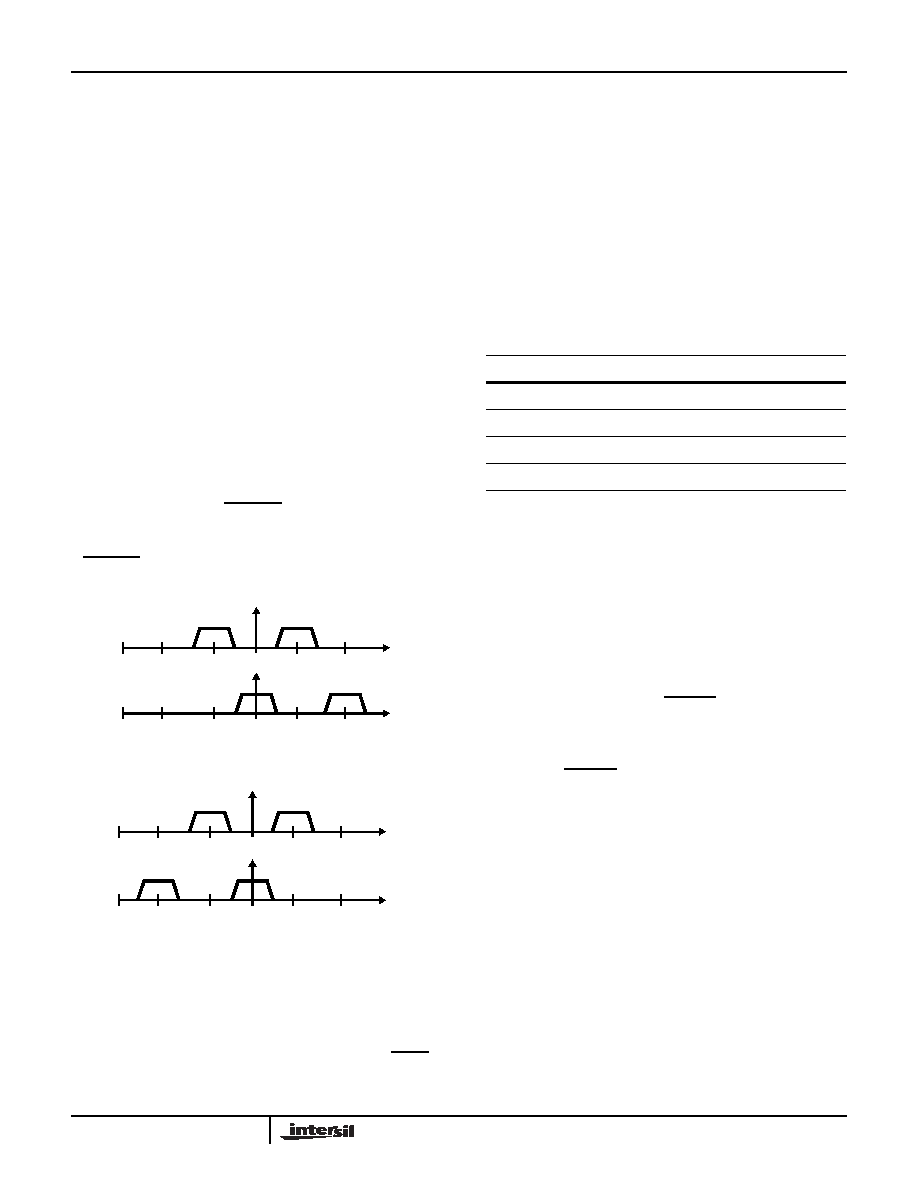
In the above operation, a positive fS/4 spectral shift is
imparted on the quadrature input which causes the upper
sideband of the resulting real output to be defined by the
spectral content of the input signal as shown in Figure 3. For
added flexibility, the Up Convert processor may be
configured to impart a negative fS/4 shift on the quadrature
input which generates a real output whose lower sideband is
defined the spectrum of the quadrature input as shown in
Figure 4. The state of the USB/LSB control input determines
the direction of the spectral shift. If this input is set “High”, a
positive fS/4 shift is introduced by the Up Convert Processor.
If USB/LSB is asserted “Low”, a negative fS/4 spectral shift
is introduced.
The Up Convert Processor implements the up convert
operation by multiplying the in-phase and quadrature
samples on the upper and lower processing legs by the
nonzero sine and cosine terms in the above expression. The
resulting data is then multiplexed together in the Output Flow
Controller to yield the real output sample stream. The SYNC
control input may be used to align the zero degree phase of
the Up Convert LO with a particular input sample as
described in the Operational Modes Section.
The Up Convert Processor also scales the data streams
output from the Filter Processor as required by the
operational mode. In the modes which employ interpolation,
the Up Convert Processor scales the Filter Processor’s
output by two to compensate for the attenuation of one half
caused by the interpolation process. In down convert and
decimate mode, the filter processor output is also scaled by
two to compensate for the attenuation introduced by the
down covert process. The scaling operations performed are
summarized in Table 4.
Output Data Flow Controller
The Output Flow Controller routes data to the AOUT0-15
and BOUT0-15 output depending on mode of operation. In
decimate by two mode (MODE1-0 = 00), output from the
filter processor’s polyphase branches are summed and
output through AOUT0-15. In Down Convert and Decimate
mode (MODE1-0 = 10), real and imaginary data streams
produced by the down convert process pass are output
directly to AOUT0-15 and BOUT0-15 respectively. In the two
modes using interpolation, MODE1-0 = 01 or 11, with
internal multiplexing enabled, INT/EXT set high, data sam
ples output from the polyphase branches are internally
multiplexed into a single stream and output via AOUT0-15. If
a mode using interpolation is specified together with external
multiplexing, INT/EXT set low, the data stream multiplexing
is performed off chip and the data on the upper and lower
processing legs is output through AOUT0-15 and BOUT0-15.
The Output Data Flow Controller also sets the binary format
and precision of the two 16-bit outputs. The data format is
specified as either two’s complement (FMT input low) or
offset binary (FMT input high). The precision of the output
data is set from 8-bits to 16-bits via the round control inputs,
RND2-0. The RND2-0 inputs round the output data to a
precision ranging from 8-bits to 16-bits as specified in Table
5. Saturation logic is incorporated in the output flow
controller to insure that numerical growth associated with a
worst case signal input or rounding condition saturates to a
16-bit value.
FIGURE 3. fS/4 POSITIVE SHIFT: UP CONVERSION
FIGURE 4. fS/4 NEGATIVE SHIFT: DOWN CONVERSION
0fS/4
-fS/4
-fS/2
fS/2
0fS/4
-fS/4
-fS/2
fS/2
0fS/4
-fS/4
-fS/2
fS/2
0fS/4
-fS/4
-fS/2
fS/2
TABLE 4. SCALE FACTORS APPLIED BY UP CONVERT
PROCESSOR vs MODE
MODE
SCALE FACTOR
Decimate by Two (MODE1-0 = 00)
1.0
Interpolate by Two (MODE1-0 = 01)
2.0
Down Convert and Decimate (MODE1-0 = 10)
2.0
Quadrature to Real (MODE1-0 = 11)
2.0
HSP43216
相關(guān)PDF資料 |
PDF描述 |
|---|---|
| HSP43220JC-33Z | IC DECIMATING DGTL FILTER 84PLCC |
| IA188EM-PTQ100I-R-03 | IC MCU 8/16BIT 40MHZ 100TQFP |
| IA188ES-PTQ100I-R-03 | IC MCU 8/16BIT 40MHZ 100TQFP |
| IA6805E2PLC44IR0 | IC MCU 8BIT 5MHZ 44PLCC |
| IA82050-PDW28I-R-01 | IC ASYNCHRONOUS SERIAL CTRL |
相關(guān)代理商/技術(shù)參數(shù) |
參數(shù)描述 |
|---|---|
| HSP43216JI-52 | 制造商:Rochester Electronics LLC 功能描述:- Bulk |
| HSP43216VC-52 | 功能描述:有源濾波器 HALFBAND FILTER 100 PIN PQFP,COMM RoHS:否 制造商:Maxim Integrated 通道數(shù)量:1 截止頻率:150 KHz 電源電壓-最大:11 V 電源電壓-最小:4.74 V 最大工作溫度:+ 85 C 安裝風(fēng)格:Through Hole 封裝 / 箱體:PDIP N 封裝:Tube |
| HSP43216VC-52Z | 功能描述:有源濾波器 W/ANNEAL HALFB & FILER 100 PIN PQFP RoHS:否 制造商:Maxim Integrated 通道數(shù)量:1 截止頻率:150 KHz 電源電壓-最大:11 V 電源電壓-最小:4.74 V 最大工作溫度:+ 85 C 安裝風(fēng)格:Through Hole 封裝 / 箱體:PDIP N 封裝:Tube |
| HSP43220 | 制造商:INTERSIL 制造商全稱:Intersil Corporation 功能描述:Decimating Digital Filter |
| HSP43220/883 | 制造商:INTERSIL 制造商全稱:Intersil Corporation 功能描述:Decimating Digital Filter |
發(fā)布緊急采購(gòu),3分鐘左右您將得到回復(fù)。