- 您現(xiàn)在的位置:買賣IC網(wǎng) > PDF目錄370740 > HY5PS12823LF 64Mx8|1.8V|8K|D43/D44/D54/D55|DDR II SDRAM - 512M PDF資料下載
參數(shù)資料
| 型號: | HY5PS12823LF |
| 英文描述: | 64Mx8|1.8V|8K|D43/D44/D54/D55|DDR II SDRAM - 512M |
| 中文描述: | 64Mx8 | 1.8 | 8K的| D43/D44/D54/D55 |的DDR II內(nèi)存- 512M |
| 文件頁數(shù): | 41/66頁 |
| 文件大小: | 862K |
| 代理商: | HY5PS12823LF |
第1頁第2頁第3頁第4頁第5頁第6頁第7頁第8頁第9頁第10頁第11頁第12頁第13頁第14頁第15頁第16頁第17頁第18頁第19頁第20頁第21頁第22頁第23頁第24頁第25頁第26頁第27頁第28頁第29頁第30頁第31頁第32頁第33頁第34頁第35頁第36頁第37頁第38頁第39頁第40頁當(dāng)前第41頁第42頁第43頁第44頁第45頁第46頁第47頁第48頁第49頁第50頁第51頁第52頁第53頁第54頁第55頁第56頁第57頁第58頁第59頁第60頁第61頁第62頁第63頁第64頁第65頁第66頁

Rev. 0.52/Nov. 02 41
HY5PS12423(L)F
HY5PS12823(L)F
HY5PS121623(L)F
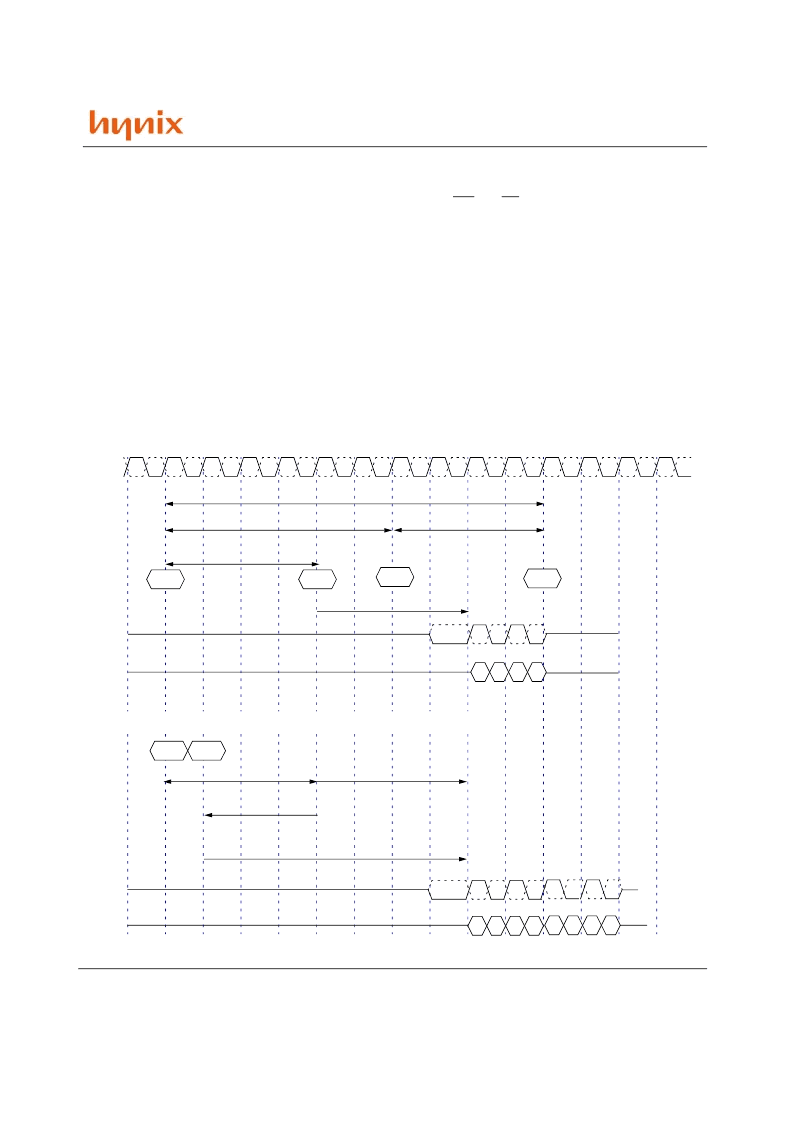
Burst Read Opeation
Burst read command is issued by activating CS and CAS, deactivating RAS and WE at the rising edge of clock. Bank
address and column address provided on inputs BA0~BA1 and A0~A13 selects the bank and starting column address
for burst operation. Before the burst read command, the bank must be activated earlier. First burst data come out RL
delay later when burst read command is issued. Burst read command to data output delay is determined by RL (Read
Latency), where AL + CL.
DDR-II SDRAM has been implemented with differential data strobe signal pair (/DQS and DQS) which toggles high and
low during burst with the same frequency as clock. DQS pair (/DQS) is driven by the DDR-II SDRAM along with output
data. Differenital pair of data strobe is driven to low/high state from Hi-Z state one clock prioir to valid data. The initial
state on DQS (/DQS) is called as the read preamble. Optional single ended strobe operation is supported by EMRS.
DDR-II SDRAM do not allow any interruption of read burst due to the nature of 4bit prepatch architecture. Unlike DDR-
I SDRAM, read burst interupt by precharge, another read command or burst stop is prohibited during read burst. Burst
read command to the another bank can be given with having activated that bank where RAS to RAS delay (tRRD) is
satisfied.
/CK
CK
Active
Q0 Q1 Q2 Q3
Read
tRCD = 4clks
CAS latency = 4clks
Active
Q0 Q1 Q2 Q3
Read
Read latency = 7clks
Additive Latency = 3clks
CMD
DQS
DQ
CMD
DQS
DQ
Q4 Q5 Q6 Q7
tRCD
BPRE
Active
tRP
tRAS
tRC
tRCD=4clks
CL=4clks, AL=3clk
BL=8
CAS latency = 4clks
tRCD=4CLKs, tRP=4CLKs, CL=4CLKs, AL=0CLK, BL=4
tRCD=4CLKs, tRP=4CLKs, CL=4CLKs, AL=3CLK, BL=8
相關(guān)PDF資料 |
PDF描述 |
|---|---|
| HY5P | Current Transducers HY 5 to 25-P/SP1 |
| HY5R256HC | -|2.5V|8K|40|Direct RDRAM - 256M |
| HY5R288HC | -|2.5V|8K|40|Direct RDRAM - 288M |
| HY5V16CF | 1Mx16|3.3V|4K|H|SDR SDRAM - 16M |
| HY5V16CF-H | x16 SDRAM |
相關(guān)代理商/技術(shù)參數(shù) |
參數(shù)描述 |
|---|---|
| HY5PS1G1631AFP | 制造商:HYNIX 制造商全稱:Hynix Semiconductor 功能描述:1Gb DDR2 SDRAM |
| HY5PS1G1631AFP-Y5 | 制造商:HYNIX 制造商全稱:Hynix Semiconductor 功能描述:1Gb DDR2 SDRAM |
| HY5PS1G1631ALFP | 制造商:HYNIX 制造商全稱:Hynix Semiconductor 功能描述:1Gb DDR2 SDRAM |
| HY5PS1G1631ALFP-Y5 | 制造商:HYNIX 制造商全稱:Hynix Semiconductor 功能描述:1Gb DDR2 SDRAM |
| HY5PS1G1631CFP | 制造商:HYNIX 制造商全稱:Hynix Semiconductor 功能描述:1Gb DDR2 SDRAM |
發(fā)布緊急采購,3分鐘左右您將得到回復(fù)。