- 您現在的位置:買賣IC網 > PDF目錄67685 > ICS1890Y-14 1 CHANNEL(S), 100M bps, SERIAL COMM CONTROLLER, PQFP64 PDF資料下載
參數資料
| 型號: | ICS1890Y-14 |
| 元件分類: | 微控制器/微處理器 |
| 英文描述: | 1 CHANNEL(S), 100M bps, SERIAL COMM CONTROLLER, PQFP64 |
| 封裝: | TQFP-64 |
| 文件頁數: | 28/66頁 |
| 文件大小: | 1749K |
| 代理商: | ICS1890Y-14 |
第1頁第2頁第3頁第4頁第5頁第6頁第7頁第8頁第9頁第10頁第11頁第12頁第13頁第14頁第15頁第16頁第17頁第18頁第19頁第20頁第21頁第22頁第23頁第24頁第25頁第26頁第27頁當前第28頁第29頁第30頁第31頁第32頁第33頁第34頁第35頁第36頁第37頁第38頁第39頁第40頁第41頁第42頁第43頁第44頁第45頁第46頁第47頁第48頁第49頁第50頁第51頁第52頁第53頁第54頁第55頁第56頁第57頁第58頁第59頁第60頁第61頁第62頁第63頁第64頁第65頁第66頁
34
ICS1890
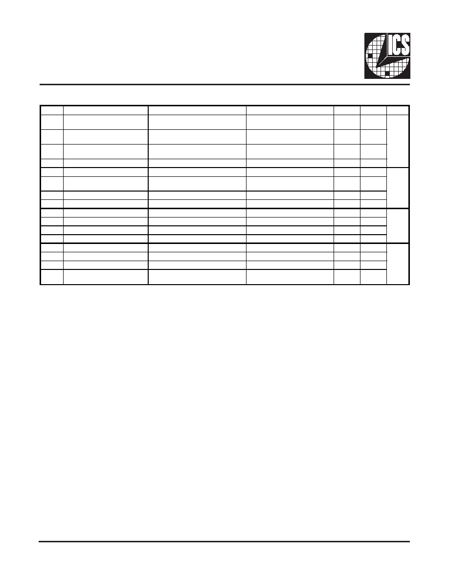
Extended Control Register 2 (register 19 [0X13])
Extended Control Register 2 (register 19)
Node/Repeater Configuration (bit 15)
This bit directly reflects the status of the NOD/REP pin.
When this bit is logic zero, the device will default to Node
operation. SQE test will default to on. Carrier sense in half
duplex mode will be on transmit or receive activity.
When this bit is logic one, the device will default to Repeater
operation. SQE test will default to off. Carrier sense in half
duplex mode will be on receive activity only.
Hardware/Software Priority Status (bit 14)
This bit directly reflects the status of the HW/SW pin.
When this bit is logic zero, hardware pins have priority over
software settings. The 10/100SEL pin becomes an input and
controls speed selection. The DPXSEL pin becomes an input
and controls duplex selection. The ANSEL pin becomes an
input and chooses configuration with or without Auto-
Negotiation.
When configuration through Auto-Negotiation is selected,
the DPXSEL and 10/100SEL settings control the Auto-
Negotiation register 4 default settings and Auto-Negotiation
is enabled. When configuration without Auto-Negotiation is
selected, DPXSEL controls the duplex setting and 10/100SEL
controls the data rate setting.
When this bit is a logic one, software bits have priority over
hardware pin settings. The 10/100SEL pin becomes an output
indicating the link speed when LSTA the link is established
and parallels bit (17:15). The DPXSEL pin becomes an output
indicating the link duplex state when the link is established
and parallels bit (17:14). The ANSEL pin becomes an output
indicating whether auto-negotiation is being used and parallels
bit(0:12).
Bit
Definition
When bit=0
When bit=1
Access
Default
Hex
15
Node/Repeater Mode
Node Mode
Repeater Mode
RO
NOD/-
REP
14
Hardware/Software Priority
Hardware Priority
Software Priority
RO
HW/S-
W
13
Link Partner Supports
Remote Fault
unknown
partner supports Remote Fault
RO
0
12
Reserved for ICS
Read unspecified
RW /0
-
11
Reserved for ICS
Read unspecified
RW /0
-
10
Transmitted Remote Fault
Status
RF bit in transmitted LCW=0
RF bit in transmitted LCW=1
RW /0
-
9
Reserved for ICS
Read unspecified
RW /0
-
8
Reserved for ICS
Read unspecified
RW /0
-
7
Reserved for ICS
Read unspecified
RW /0
-
6
Reserved for ICS
Read unspecified
RW /0
-
5
Reserved for ICS
Read unspecified
RW /0
-
4
A-N Power-up Remote Fault
Normal
Remote Fault on Power-up
RW
0
3
Reserved for ICS
Read unspecified
RW /0
0
2
Reserved for ICS
Read unspecified
RW /0
-
1
Reserved for ICS
Read unspecified
RW /0
0
Automatic 100Base-TX
Power-down
Never Power-down automatically
Power-down automatically
RW
1
相關PDF資料 |
PDF描述 |
|---|---|
| ICS2059GI-02 | 27 MHz, VIDEO CLOCK GENERATOR, PDSO16 |
| ICS2304NZGI-1T | 2304 SERIES, LOW SKEW CLOCK DRIVER, 4 TRUE OUTPUT(S), 0 INVERTED OUTPUT(S), PDSO8 |
| ICS2304NZG-1LF | 2304 SERIES, LOW SKEW CLOCK DRIVER, 4 TRUE OUTPUT(S), 0 INVERTED OUTPUT(S), PDSO8 |
| ICS252MI-XXLF | 200 MHz, OTHER CLOCK GENERATOR, PDSO8 |
| ICS252MI-XX | 200 MHz, OTHER CLOCK GENERATOR, PDSO8 |
相關代理商/技術參數 |
參數描述 |
|---|---|
| ICS1890Y-4 | 制造商:ICS 功能描述:1890Y-4 |
| ICS1891 | 制造商:未知廠家 制造商全稱:未知廠家 功能描述:LAN Transceiver |
| ICS1891Y | 制造商:未知廠家 制造商全稱:未知廠家 功能描述:LAN Transceiver |
| ICS1892 | 制造商:ICS 制造商全稱:ICS 功能描述:10Base-T/100Base-TX Integrated PHYceiver |
| ICS1892Y | 制造商:ICS 制造商全稱:ICS 功能描述:10Base-T/100Base-TX Integrated PHYceiver |
發(fā)布緊急采購,3分鐘左右您將得到回復。