- 您現(xiàn)在的位置:買賣IC網(wǎng) > PDF目錄367854 > PDI1394L11 (NXP Semiconductors N.V.) 1394 AV Link Layer Controller(AV(音頻/視頻)鏈接層控制器) PDF資料下載
參數(shù)資料
| 型號: | PDI1394L11 |
| 廠商: | NXP Semiconductors N.V. |
| 英文描述: | 1394 AV Link Layer Controller(AV(音頻/視頻)鏈接層控制器) |
| 中文描述: | 1394影音鏈路層控制器(視聽(音頻/視頻)鏈接層控制器) |
| 文件頁數(shù): | 10/46頁 |
| 文件大小: | 294K |
| 代理商: | PDI1394L11 |
第1頁第2頁第3頁第4頁第5頁第6頁第7頁第8頁第9頁當(dāng)前第10頁第11頁第12頁第13頁第14頁第15頁第16頁第17頁第18頁第19頁第20頁第21頁第22頁第23頁第24頁第25頁第26頁第27頁第28頁第29頁第30頁第31頁第32頁第33頁第34頁第35頁第36頁第37頁第38頁第39頁第40頁第41頁第42頁第43頁第44頁第45頁第46頁
Philips Semiconductors
Product specification
PDI1394L11
1394 AV link layer controller
1997 Oct 21
10
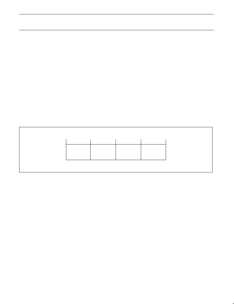
12.3.3
The bytes in each quadlet are numbered 0..3 from left (most
significant) to right (least significant) as shown in Figure 1.
To access a register at internal address N the CPU should use
addresses E:
E = 4 N
; to access the upper 8 bits of the register.
E = 4 N + 1
; to access the upper middle 8 bits of the register.
E = 4 N + 2
; to access the lower middle 8 bits of the register.
E = 4 N + 3
; to access the lower 8 bits of the register.
Byte order
12.3.4
Although entire incoming packets are stored in the receiver buffer
memory they are not randomly accessible. These buffers act like
fifos and only the frontmost (oldest) data quadlet entry is accessible
for reading. Therefore only one location (register address) is
allocated to each of the two receiver queues. Reading this location
returns the head entry of the queue, and at the same time removes
it from the queue, making the next stored data quadlet accessible.
Accessing the packet queues
With the current host interface such a read is in fact a move
operation of the data quadlet from the queue to the read shadow
register. Once the data is copied into the read shadow register it is
no longer available in the queue itself so the CPU should always
read all 4 bytes before attempting any other read access (be careful
with interrupt handlers for AVLink!).
A similar argument applies to the transmitter queues. Data cannot
be written arbitrarily, but only to the next available free location.
Since the transmitter needs to know when the packet is complete
(all data stored in memory, so that it may start the arbitration
process on the 1394 bus) two separate register locations are
reserved per transmitter queue: one to write all but the last packet
quadlet to, and one to write the last quadlet of every packet to.
Writing to any of these register locations stores the data in the
queue and makes the next memory location accessible for writing.
NOTE:
1. Because of the way it is implemented memory access is not
always immediate; consequently it may take some time before
the next data quadlet in the queue is accessible after reading or
writing the current one. Status flags are provided to the CPU to
indicate availability.
SV00656
29 28 272625 24 23 22 212019 18 1716 15 1413 12 11 10 9 8 7 6 5 4 3 2 1 0
BYTE 0
BYTE 1
BYTE 3
3130
BYTE 2
Figure 1. Byte order in quadlets as implemented in the host interface
12.3.5
The CPU interface is directly compatible with an 8051
microcontroller. It uses a separate HIF RD_N and HIF WR_N inputs
and a HIF CS_N chip select line, all of which are active LOW. There
are 9 address inputs (HIF A0..HIF A8) and 8 data in/out lines
HIF D0..HIF D7. An open drain HIF INT_N output is used to signal
interrupts to the CPU.
The CPU bus interface signals
The CPU is not required to run at a clock that is synchronous to the
1394 base clock. The control signals will be resampled by the host
interface before being used internally.
An access through the host interface starts when HIF CS_N = 0 and
either HIF WR_N = 0 or HIF RD_N = 0. Typically the chip select
signal is derived from the upper address lines of the CPU (address
decode stage), but it could also be connected to a port pin of the
CPU to avoid the need for an external address decoder in very
simple CPU systems. When both HIF CS_N = 0 and HIF RD_N = 0
the host interface will start a read access cycle, so the cycle is
triggered at the falling edge of either HIF CS_N or HIF RD_N,
whichever is later.
Very shortly after the start of the cycle, the selected byte in the
read
shadow register
will be output (indicated in Figure 2 as RSR
O
). If
HIF A8 is asserted then the target register value will be copied into
the
read shadow register
, leading to a new value RSR
n
some time
later in the read cycle. If HIF A8 is LOW, then the
read shadow
register
will not change.
A write access starts when the later of HIF CS_N and HIF WR_N
becomes LOW (see Figure 3). Data is written to the shadow
register, following which, if HIF A8 is asserted, the shadow register
value is copied to the addressed register.
NOTES:
1. The time between the end of any access and the start of the next
access must be at least t
CH
which needs to be greater than
(2 x SCLK).
2. When HIF A8 = 0 for either write or read access the address bits
HIF A2..HIF A7 are ignored.
3. If both HIF WR_N = 0 and HIF RD_N = 0 while HIF CS_N = 0,
then a write cycle takes place.
相關(guān)PDF資料 |
PDF描述 |
|---|---|
| PDI1394L21 | Full Duplex AV Link Layer Ccontroller(全雙工AV鏈接層控制器) |
| PDI1394L41 | Content Protection AV Link Layer(內(nèi)容可保護(hù)的AV鏈接層控制器) |
| PDI1394P21 | 3-port Physical Layer Interface(三端口物理層接口) |
| PDI1394P22 | 3-port Physical Layer Interface(三端口物理層接口) |
| PDI1394P24 | 2-port 400 Mbps physical layer interface(2端口 400 Mbps物理層接口) |
相關(guān)代理商/技術(shù)參數(shù) |
參數(shù)描述 |
|---|---|
| PDI1394L11BA | 制造商:PHILIPS 制造商全稱:NXP Semiconductors 功能描述:1394 AV link layer controller |
| PDI1394L11BA-S | 制造商:未知廠家 制造商全稱:未知廠家 功能描述:IEEE 1394 (Firewire) Bus Interface/Controller |
| PDI1394L21 | 制造商:PHILIPS 制造商全稱:NXP Semiconductors 功能描述:1394 full duplex AV link layer controller |
| PDI1394L21BE | 制造商:PHILIPS 制造商全稱:NXP Semiconductors 功能描述:1394 full duplex AV link layer controller |
| PDI1394L21BP | 制造商:PHILIPS 制造商全稱:NXP Semiconductors 功能描述:1394 full duplex AV link layer controller |
發(fā)布緊急采購,3分鐘左右您將得到回復(fù)。