- 您現(xiàn)在的位置:買賣IC網(wǎng) > PDF目錄372109 > SAA4979H (NXP SEMICONDUCTORS) Sample rate converter with embedded high quality dynamic noise reduction and expansion port PDF資料下載
參數(shù)資料
| 型號: | SAA4979H |
| 廠商: | NXP SEMICONDUCTORS |
| 元件分類: | 消費家電 |
| 英文描述: | Sample rate converter with embedded high quality dynamic noise reduction and expansion port |
| 中文描述: | SPECIALTY CONSUMER CIRCUIT, PQFP128 |
| 封裝: | 28 X 28 X 3.40 MM, PLASTIC, QFP-128 |
| 文件頁數(shù): | 21/52頁 |
| 文件大?。?/td> | 224K |
| 代理商: | SAA4979H |
第1頁第2頁第3頁第4頁第5頁第6頁第7頁第8頁第9頁第10頁第11頁第12頁第13頁第14頁第15頁第16頁第17頁第18頁第19頁第20頁當前第21頁第22頁第23頁第24頁第25頁第26頁第27頁第28頁第29頁第30頁第31頁第32頁第33頁第34頁第35頁第36頁第37頁第38頁第39頁第40頁第41頁第42頁第43頁第44頁第45頁第46頁第47頁第48頁第49頁第50頁第51頁第52頁

2002 May 28
21
Philips Semiconductors
Product specification
Sample rate converter with embedded high quality
dynamic noise reduction and expansion port
SAA4979H
7.6.8
O
UTPUT
/I
NPUT ENABLE
2
The Output/Input Enable 2 (OIE2) signal is intended for
control of one or two external field memories at input
channel 2 in picture-in-picture applications. It can be
directly set or reset via the microcontroller.
7.6.9
R
ESET READ
2
The Reset Read 2 (RSTR2) signal is intended for control
of the read access of an external field memory at input
channel 2 in picture-in-picture applications. It is derived
from the internal vertical reference signal of the main
channel.
7.6.10
R
ESET WRITE
2
The Reset Write 2 (RSTW2) input is used in
picture-in-picture applications with an external field
memory at input channel 2, and has to be provided by an
external circuit which controls the field memory write
access.
7.7
Line-locked clock generation
An internal PLL generates the 32 MHz line-locked display
clock CLK32. The PLL consists of a ring oscillator, DTO
and digital control loop. The PLL characteristic is
controlled by means of the microcontroller.
7.8
Boundary scan test
The SAA4979H has built-in logic and 6 dedicated pins to
support boundary scan testing which allows board testing
without special hardware (nails). The SAA4979H follows
the “IEEE Std. 1149.1 - Standard Test Access Port and
Boundary-Scan Architecture”set by the Joint Test Action
Group (JTAG) chaired by Philips.
The 6 special pins are Test Mode Select (TMS), Test
Clock (TCK), Test Reset (TRST), Test Data Input (TDI),
Boundary-scan Compliant Enable (BCE) and Test Data
Output (TDO). To achieve compliance to the
“IEEE Std. 1149.1”a logic HIGH has to be applied to the
BCE pin. Internal pull-up resistors at the input pins TMS,
TRST and TDI are not implemented.
8
CONTROL REGISTER DESCRIPTION
8.1
Host interface detail
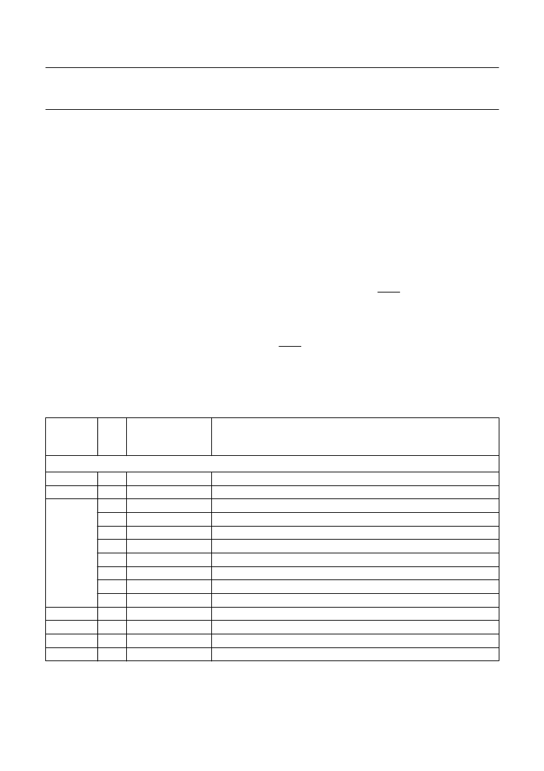
Table 4
Write register at 1f
H
HOST
ADDRESS
(HEX)
BIT
NAME
DESCRIPTION
Host address 0102H to 011CH (system control)
0102
0103
0104
0 to 7 weint_vstart
0 to 7 weint_vstop
0
weint_vstart (MSB)
1
weint_vstop (MSB)
2
fm1_still
3
pip_2fm_dc
4
sfr
5
sfm
6
re2_vstart (MSB)
7
re2_vstop (MSB)
0 to 7 re2_vstart
0 to 7 re2_vstop
0 to 7 re2_hstart
0 to 7 re2_hstop
write enable internal memory vertical start (lower 8 of 9 bits)
write enable internal memory vertical stop (lower 8 of 9 bits)
write enable internal memory vertical start (MSB)
write enable internal memory vertical stop (MSB)
still picture mode; 0 = normal mode, 1 = still picture mode
direct controlled PIP mode; 0 = normal mode, 1 = direct mode
field recognition mode; 0 = normal mode, 1 = inverse mode
single field mode; 0 = normal mode, 1 = single field mode
read enable PIP window vertical start (MSB)
read enable PIP window vertical stop (MSB)
read enable PIP window vertical start (lower 8 of 9 bits)
read enable PIP window vertical stop (lower 8 of 9 bits)
read enable PIP window horizontal start (lower 8 of 10 bits)
read enable PIP window horizontal stop (lower 8 of 10 bits)
0105
0106
0107
0108
相關(guān)PDF資料 |
PDF描述 |
|---|---|
| SAA4981 | Monolithic integrated 16 : 9 compressor |
| SAA4981T | Monolithic integrated 16 : 9 compressor |
| SAA4993H | Field and line rate converter with noise reduction |
| SAA4994H | Field and line rate converter with noise reduction |
| SAA4998H | Field and line rate converter with noise reduction and embedded memory |
相關(guān)代理商/技術(shù)參數(shù) |
參數(shù)描述 |
|---|---|
| SAA4981 | 制造商:PHILIPS 制造商全稱:NXP Semiconductors 功能描述:Monolithic integrated 16 : 9 compressor |
| SAA4981T | 制造商:PHILIPS 制造商全稱:NXP Semiconductors 功能描述:Monolithic integrated 16 : 9 compressor |
| SAA4990 | 制造商:PHILIPS 制造商全稱:NXP Semiconductors 功能描述:Progressive scan-Zoom and Noise reduction IC PROZONIC |
| SAA4990H | 制造商:PHILIPS 制造商全稱:NXP Semiconductors 功能描述:Progressive scan-Zoom and Noise reduction IC PROZONIC |
| SAA4992 | 制造商:PHILIPS 制造商全稱:NXP Semiconductors 功能描述:Field and line rate converter with noise reduction |
發(fā)布緊急采購,3分鐘左右您將得到回復(fù)。