- 您現(xiàn)在的位置:買賣IC網(wǎng) > PDF目錄300038 > TMS320C2812ZHHS (TEXAS INSTRUMENTS INC) 16-BIT, 150 MHz, OTHER DSP, PBGA179 PDF資料下載
參數(shù)資料
| 型號: | TMS320C2812ZHHS |
| 廠商: | TEXAS INSTRUMENTS INC |
| 元件分類: | 數(shù)字信號處理 |
| 英文描述: | 16-BIT, 150 MHz, OTHER DSP, PBGA179 |
| 封裝: | LEAD FREE, BGA-179 |
| 文件頁數(shù): | 38/156頁 |
| 文件大小: | 1826K |
| 代理商: | TMS320C2812ZHHS |
第1頁第2頁第3頁第4頁第5頁第6頁第7頁第8頁第9頁第10頁第11頁第12頁第13頁第14頁第15頁第16頁第17頁第18頁第19頁第20頁第21頁第22頁第23頁第24頁第25頁第26頁第27頁第28頁第29頁第30頁第31頁第32頁第33頁第34頁第35頁第36頁第37頁當前第38頁第39頁第40頁第41頁第42頁第43頁第44頁第45頁第46頁第47頁第48頁第49頁第50頁第51頁第52頁第53頁第54頁第55頁第56頁第57頁第58頁第59頁第60頁第61頁第62頁第63頁第64頁第65頁第66頁第67頁第68頁第69頁第70頁第71頁第72頁第73頁第74頁第75頁第76頁第77頁第78頁第79頁第80頁第81頁第82頁第83頁第84頁第85頁第86頁第87頁第88頁第89頁第90頁第91頁第92頁第93頁第94頁第95頁第96頁第97頁第98頁第99頁第100頁第101頁第102頁第103頁第104頁第105頁第106頁第107頁第108頁第109頁第110頁第111頁第112頁第113頁第114頁第115頁第116頁第117頁第118頁第119頁第120頁第121頁第122頁第123頁第124頁第125頁第126頁第127頁第128頁第129頁第130頁第131頁第132頁第133頁第134頁第135頁第136頁第137頁第138頁第139頁第140頁第141頁第142頁第143頁第144頁第145頁第146頁第147頁第148頁第149頁第150頁第151頁第152頁第153頁第154頁第155頁第156頁
Electrical Specifications
132
April 2001 Revised October 2005
SPRS174M
6.27
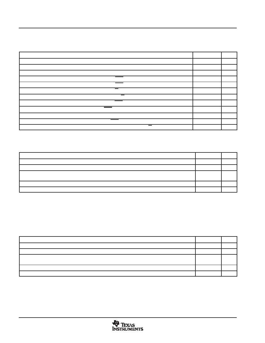
External Interface Ready-on-Write Timing With One External Wait State
Table 637. External Memory Interface Write Switching Characteristics (Ready-on-Write, 1 Wait State)
PARAMETER
MIN
MAX
UNIT
td(XCOH-XZCSL)
Delay time, XCLKOUT high to zone chip-select active low
1
ns
td(XCOHL-XZCSH)
Delay time, XCLKOUT high or low to zone chip-select inactive high
2
3
ns
td(XCOH-XA)
Delay time, XCLKOUT high to address valid
2
ns
td(XCOHL-XWEL)
Delay time, XCLKOUT high/low to XWE low
2
ns
td(XCOHL-XWEH)
Delay time, XCLKOUT high/low to XWE high
2
ns
td(XCOH-XRNWL)
Delay time, XCLKOUT high to XR/W low
1
ns
td(XCOHL-XRNWH)
Delay time, XCLKOUT high/low to XR/W high
2
1
ns
ten(XD)XWEL
Enable time, data bus driven from XWE low
0
ns
td(XWEL-XD)
Delay time, data valid after XWE active low
4
ns
th(XA)XZCSH
Hold time, address valid after zone chip-select inactive high
ns
th(XD)XWE
Hold time, write data valid after XWE inactive high
TW2
ns
tdis(XD)XRNW
Maximum time for DSP to release the data bus after XR/W inactive high
4
ns
During inactive cycles, the XINTF address bus will always hold the last address put out on the bus. This includes alignment cycles.
TW = trail period, write access (see Table 628)
Table 638. Synchronous XREADY Timing Requirements (Ready-on-Write, 1 Wait State)§
MIN
MAX
UNIT
tsu(XRDYsynchL)XCOHL
Setup time, XREADY (synchronous) low before XCLKOUT high/low
15
ns
th(XRDYsynchL)
Hold time, XREADY (synchronous) low
12
ns
te(XRDYsynchH)
Earliest time XREADY (synchronous) can go high before the sampling XCLKOUT
edge
3
ns
tsu(XRDYsynchH)XCOHL
Setup time, XREADY (synchronous) high before XCLKOUT high/low
15
ns
th(XRDYsynchH)XZCSH
Hold time, XREADY (synchronous) held high after zone chip select high
0
ns
§ The first XREADY (synchronous) sample occurs with respect to E in Figure 634:
E =(XWRLEAD + XWRACTIVE) tc(XTIM)
When first sampled, if XREADY (synchronous) is found to be high, then the access will complete. If XREADY (synchronous) is found to be low,
it will be sampled again each tc(XTIM) until it is found to be high.
For each sample, setup time from the beginning of the access can be calculated as:
D =(XWRLEAD + XWRACTIVE +n 1) tc(XTIM) tsu(XRDYsynchL)XCOHL
where n is the sample number: n = 1, 2, 3, and so forth.
Table 639. Asynchronous XREADY Timing Requirements (Ready-on-Write, 1 Wait State)
MIN
MAX
UNIT
tsu(XRDYasynchL)XCOHL
Setup time, XREADY (asynchronous) low before XCLKOUT high/low
11
ns
th(XRDYasynchL)
Hold time, XREADY (asynchronous) low
8
ns
te(XRDYasynchH)
Earliest time XREADY (asynchronous) can go high before the sampling
XCLKOUT edge
3
ns
tsu(XRDYasynchH)XCOHL
Setup time, XREADY (asynchronous) high before XCLKOUT high/low
11
ns
th(XRDYasynchH)XZCSH
Hold time, XREADY (asynchronous) held high after zone chip select high
0
ns
The first XREADY (synchronous) sample occurs with respect to E in Figure 635:
E = (XWRLEAD + XWRACTIVE 2) tc(XTIM)
When first sampled, if XREADY (asynchronous) is found to be high, then the access will complete. If XREADY (asynchronous) is found to be
low, it will be sampled again each tc(XTIM) until it is found to be high.
For each sample, setup time from the beginning of the access can be calculated as:
D = (XWRLEAD + XWRACTIVE 3 + n) tc(XTIM) tsu(XRDYasynchL)XCOHL
where n is the sample number: n = 1, 2, 3, and so forth.
相關PDF資料 |
PDF描述 |
|---|---|
| TMS320C6747BZKB4 | OTHER DSP, PBGA256 |
| TMS320LF2407APGEA | 16-BIT, 20 MHz, OTHER DSP, PQFP144 |
| TMS426409AP-60DJ | 4M X 4 EDO DRAM, 60 ns, PDSO24 |
| TMS426809AP-70DGC | 2M X 8 EDO DRAM, 70 ns, PDSO28 |
| TMS44400DJ-80 | 1M X 4 FAST PAGE DRAM, 80 ns, PDSO20 |
相關代理商/技術參數(shù) |
參數(shù)描述 |
|---|---|
| TMS320C28341 | 制造商:TI 制造商全稱:Texas Instruments 功能描述:Delfino Microcontrollers |
| TMS320C28341ZEPQ | 制造商:Texas Instruments 功能描述:DELFINO MICROCONTROLLER - Trays |
| TMS320C28341ZFEQ | 功能描述:32位微控制器 - MCU Delfino MCU RoHS:否 制造商:Texas Instruments 核心:C28x 處理器系列:TMS320F28x 數(shù)據(jù)總線寬度:32 bit 最大時鐘頻率:90 MHz 程序存儲器大小:64 KB 數(shù)據(jù) RAM 大小:26 KB 片上 ADC:Yes 工作電源電壓:2.97 V to 3.63 V 工作溫度范圍:- 40 C to + 105 C 封裝 / 箱體:LQFP-80 安裝風格:SMD/SMT |
| TMS320C28341ZFET | 功能描述:32位微控制器 - MCU Delfino MCU RoHS:否 制造商:Texas Instruments 核心:C28x 處理器系列:TMS320F28x 數(shù)據(jù)總線寬度:32 bit 最大時鐘頻率:90 MHz 程序存儲器大小:64 KB 數(shù)據(jù) RAM 大小:26 KB 片上 ADC:Yes 工作電源電壓:2.97 V to 3.63 V 工作溫度范圍:- 40 C to + 105 C 封裝 / 箱體:LQFP-80 安裝風格:SMD/SMT |
| TMS320C28341ZHHT | 功能描述:32位微控制器 - MCU Delfino MCU RoHS:否 制造商:Texas Instruments 核心:C28x 處理器系列:TMS320F28x 數(shù)據(jù)總線寬度:32 bit 最大時鐘頻率:90 MHz 程序存儲器大小:64 KB 數(shù)據(jù) RAM 大小:26 KB 片上 ADC:Yes 工作電源電壓:2.97 V to 3.63 V 工作溫度范圍:- 40 C to + 105 C 封裝 / 箱體:LQFP-80 安裝風格:SMD/SMT |
發(fā)布緊急采購,3分鐘左右您將得到回復。