- 您現(xiàn)在的位置:買賣IC網(wǎng) > PDF目錄366550 > AM79C940 (Advanced Micro Devices, Inc.) Media Access Controller for Ethernet (MACE) PDF資料下載
參數(shù)資料
| 型號(hào): | AM79C940 |
| 廠商: | Advanced Micro Devices, Inc. |
| 英文描述: | Media Access Controller for Ethernet (MACE) |
| 中文描述: | 媒體訪問(wèn)控制器(MACE發(fā)生以太網(wǎng)) |
| 文件頁(yè)數(shù): | 45/122頁(yè) |
| 文件大小: | 914K |
| 代理商: | AM79C940 |
第1頁(yè)第2頁(yè)第3頁(yè)第4頁(yè)第5頁(yè)第6頁(yè)第7頁(yè)第8頁(yè)第9頁(yè)第10頁(yè)第11頁(yè)第12頁(yè)第13頁(yè)第14頁(yè)第15頁(yè)第16頁(yè)第17頁(yè)第18頁(yè)第19頁(yè)第20頁(yè)第21頁(yè)第22頁(yè)第23頁(yè)第24頁(yè)第25頁(yè)第26頁(yè)第27頁(yè)第28頁(yè)第29頁(yè)第30頁(yè)第31頁(yè)第32頁(yè)第33頁(yè)第34頁(yè)第35頁(yè)第36頁(yè)第37頁(yè)第38頁(yè)第39頁(yè)第40頁(yè)第41頁(yè)第42頁(yè)第43頁(yè)第44頁(yè)當(dāng)前第45頁(yè)第46頁(yè)第47頁(yè)第48頁(yè)第49頁(yè)第50頁(yè)第51頁(yè)第52頁(yè)第53頁(yè)第54頁(yè)第55頁(yè)第56頁(yè)第57頁(yè)第58頁(yè)第59頁(yè)第60頁(yè)第61頁(yè)第62頁(yè)第63頁(yè)第64頁(yè)第65頁(yè)第66頁(yè)第67頁(yè)第68頁(yè)第69頁(yè)第70頁(yè)第71頁(yè)第72頁(yè)第73頁(yè)第74頁(yè)第75頁(yè)第76頁(yè)第77頁(yè)第78頁(yè)第79頁(yè)第80頁(yè)第81頁(yè)第82頁(yè)第83頁(yè)第84頁(yè)第85頁(yè)第86頁(yè)第87頁(yè)第88頁(yè)第89頁(yè)第90頁(yè)第91頁(yè)第92頁(yè)第93頁(yè)第94頁(yè)第95頁(yè)第96頁(yè)第97頁(yè)第98頁(yè)第99頁(yè)第100頁(yè)第101頁(yè)第102頁(yè)第103頁(yè)第104頁(yè)第105頁(yè)第106頁(yè)第107頁(yè)第108頁(yè)第109頁(yè)第110頁(yè)第111頁(yè)第112頁(yè)第113頁(yè)第114頁(yè)第115頁(yè)第116頁(yè)第117頁(yè)第118頁(yè)第119頁(yè)第120頁(yè)第121頁(yè)第122頁(yè)
AMD
45
Am79C940
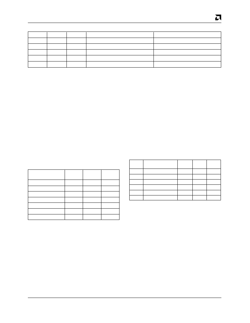
Internal/External Address Recognition Capabilities
PROM
M/
R
X
0
EAM/R
X
H
↓
H
↓
Required Timing
Received Messages
All Received Frames
All Received Frames
1
0
No timing requirements
No timing requirements
0
0
0
1
Low for 200 ns within 512-bits after SFD
No timing requirements
Physical/Logical/Broadcast Matches
Physical/Logical/Broadcast Matches
0
1
Low for 200 ns within 8-bits after DA field
All Received Frames
General Purpose Serial Interface (GPSI)
The GPSI port provides the signals necessary to pre-
sent an interface consistent with the non encoded data
functions observed to/from a LAN controller such as the
Am7990 Local Area Network Controller for Ethernet
(LANCE). The actual GPSI pins are functionally identi-
cal to some of the pins from the DAI and the EADI ports,
the GPSI replicates this type of interface.
The GPSI allows use of an external Manchester en-
coder/decoder, such as the Am7992B Serial Interface
Adapter (SIA). In addition, it allows the MACE device to
be used as a MAC sublayer engine in a repeater based
on the Am79C980 Integrated Multiport Repeater (IMR).
Simple connection to the IMR Expansion Bus allows the
MAC to view all packet data passing through a number
of interconnected IMRs, allowing statistics and network
management information to be collected.
The GPSI functional pins are duplicated as follows:
Pin Configuration for GPSI Function
LANCE
Pin
RX
RCLK
RENA
CLSN
TX
TCK
TENA
MACE
Pin
RXDAT
SRDCLK
RXCRS
CLSN
TXDAT+
STDCLK
TXEN
Function
Receive Data
Receive Clock
Receive Carrier Sense
Collision
Transmit Data
Transmit Clock
Transmit Enable
Type
I
I
I
I
O
I
O
IEEE 1149.1 Test Access Port Interface
An IEEE 1149.1 compatible boundary scan Test Access
Port is provided for board level continuity test and diag-
nostics. All digital input, output and input/output and in-
put/output pins are tested. Analog pins, including the
AUI differential driver (DO
±
) and receivers DI
±
, CI
±
),
and the crystal input (XTAL1/XTAL2) pins, are not
tested.
The following is a brief summary of the IEEE 1149.1
compatible test functions implemented in the MACE de-
vice. For additional details, consult the IEEE Standard
Test Access Port and Boundary-Scan Architecture
document (IEEE Std 1149.1–1990).
The boundary scan test circuit requires four pins (TCK,
TMS, TDI and TDO ), defined as the Test Access Port
(TAP). It includes a finite state machine (FSM), an in-
struction register, a data register array and a power on
reset circuit. Internal pull-up resistors are provided for
the TCK, TDI and TMS pins.
The TAP engine is a 16 state FSM, driven by the Test
Clock (TCK) and the Test Mode Select (TMS) pins. An
independent power on reset circuit is provided to ensure
the FSM is in the TEST_LOGIC_RESET state at
power up.
In addition to the minimum IEEE 1149.1 instruction re-
quirements (EXTEST, SAMPLE and BYPASS), three
additional instructions (IDCODE, TRI_ST and SET_I/O)
are provided to further ease board level testing. All
unused instruction codes are reserved.
IEEE 1149.1 Supported Instruction Summary
Inst
Name
Selected
Data Reg
Reg
Mode
Inst
Code
Description
EXTEST External Test
BSR
Test
0000
IDCode
ID Code Inspection
ID Reg
Normal
0001
Sample
Sample Boundary
BSR
Normal
0010
TRI_ST
Force Tristate
Bypass
Normal
0011
SET_I/0 Control BoundaryToI/0
Bypass
Test
0100
Bypass
Bypass Scan
Bypass
Normal
1111
After hardware or software reset, the IDCODE instruc-
tion is always invoked. The decoding logic provides sig-
nals to control the data flow in the DATA registers
according to the current instruction.
Each Boundary Scan Register (BSR) cell also has two
stages. A flip-flop and a latch are used in the SERIAL
SHIFT STAGE and the PARALLEL OUTPUT STAGE
respectively.
There are four possible operational modes in the BSR
cell:
(1) CAPTURE
(2) SHIFT
(3) UPDATE
(4) SYSTEM FUNCTION
相關(guān)PDF資料 |
PDF描述 |
|---|---|
| AM79C940JCW | Media Access Controller for Ethernet (MACE) |
| AM79C940KCW | Media Access Controller for Ethernet (MACE) |
| AM79C960 | PCnetTM-ISA Single-Chip Ethernet Controller |
| AM79C960KC | PCnetTM-ISA Single-Chip Ethernet Controller |
| AM79C960KCW | PCnetTM-ISA Single-Chip Ethernet Controller |
相關(guān)代理商/技術(shù)參數(shù) |
參數(shù)描述 |
|---|---|
| AM79C940_00 | 制造商:AMD 制造商全稱:Advanced Micro Devices 功能描述:Media Access Controller for Ethernet (MACE⑩) |
| AM79C940-16/25 | 制造商:未知廠家 制造商全稱:未知廠家 功能描述: |
| AM79C940-16JC | 制造商:未知廠家 制造商全稱:未知廠家 功能描述:LAN Node Controller |
| AM79C940-25JC | 制造商:未知廠家 制造商全稱:未知廠家 功能描述:LAN Node Controller |
| AM79C940AVC | 制造商:AMD 功能描述:79C940 AMD'94 SMT N6E2A |
發(fā)布緊急采購(gòu),3分鐘左右您將得到回復(fù)。