- 您現(xiàn)在的位置:買賣IC網(wǎng) > PDF目錄370260 > FW322 1394A PCI PHY/Link Open Host Controller Interface PDF資料下載
參數(shù)資料
| 型號(hào): | FW322 |
| 英文描述: | 1394A PCI PHY/Link Open Host Controller Interface |
| 中文描述: | 1394A端口物理層的PCI /鏈接開(kāi)放主機(jī)控制器接口 |
| 文件頁(yè)數(shù): | 17/148頁(yè) |
| 文件大小: | 1723K |
| 代理商: | FW322 |
第1頁(yè)第2頁(yè)第3頁(yè)第4頁(yè)第5頁(yè)第6頁(yè)第7頁(yè)第8頁(yè)第9頁(yè)第10頁(yè)第11頁(yè)第12頁(yè)第13頁(yè)第14頁(yè)第15頁(yè)第16頁(yè)當(dāng)前第17頁(yè)第18頁(yè)第19頁(yè)第20頁(yè)第21頁(yè)第22頁(yè)第23頁(yè)第24頁(yè)第25頁(yè)第26頁(yè)第27頁(yè)第28頁(yè)第29頁(yè)第30頁(yè)第31頁(yè)第32頁(yè)第33頁(yè)第34頁(yè)第35頁(yè)第36頁(yè)第37頁(yè)第38頁(yè)第39頁(yè)第40頁(yè)第41頁(yè)第42頁(yè)第43頁(yè)第44頁(yè)第45頁(yè)第46頁(yè)第47頁(yè)第48頁(yè)第49頁(yè)第50頁(yè)第51頁(yè)第52頁(yè)第53頁(yè)第54頁(yè)第55頁(yè)第56頁(yè)第57頁(yè)第58頁(yè)第59頁(yè)第60頁(yè)第61頁(yè)第62頁(yè)第63頁(yè)第64頁(yè)第65頁(yè)第66頁(yè)第67頁(yè)第68頁(yè)第69頁(yè)第70頁(yè)第71頁(yè)第72頁(yè)第73頁(yè)第74頁(yè)第75頁(yè)第76頁(yè)第77頁(yè)第78頁(yè)第79頁(yè)第80頁(yè)第81頁(yè)第82頁(yè)第83頁(yè)第84頁(yè)第85頁(yè)第86頁(yè)第87頁(yè)第88頁(yè)第89頁(yè)第90頁(yè)第91頁(yè)第92頁(yè)第93頁(yè)第94頁(yè)第95頁(yè)第96頁(yè)第97頁(yè)第98頁(yè)第99頁(yè)第100頁(yè)第101頁(yè)第102頁(yè)第103頁(yè)第104頁(yè)第105頁(yè)第106頁(yè)第107頁(yè)第108頁(yè)第109頁(yè)第110頁(yè)第111頁(yè)第112頁(yè)第113頁(yè)第114頁(yè)第115頁(yè)第116頁(yè)第117頁(yè)第118頁(yè)第119頁(yè)第120頁(yè)第121頁(yè)第122頁(yè)第123頁(yè)第124頁(yè)第125頁(yè)第126頁(yè)第127頁(yè)第128頁(yè)第129頁(yè)第130頁(yè)第131頁(yè)第132頁(yè)第133頁(yè)第134頁(yè)第135頁(yè)第136頁(yè)第137頁(yè)第138頁(yè)第139頁(yè)第140頁(yè)第141頁(yè)第142頁(yè)第143頁(yè)第144頁(yè)第145頁(yè)第146頁(yè)第147頁(yè)第148頁(yè)
Lucent Technologies Inc.
17
Data Sheet, Rev. 1
February 2001
FW322
1394A PCI PHY/Link Open Host Controller Interface
Pin Information
(continued)
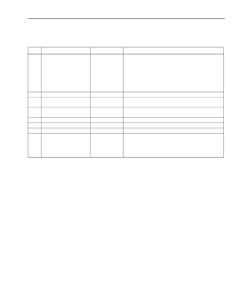
Table 1. Pin Descriptions
(continued)
Application Schematic
The application schematic presents a complete two-port, 400 Mbits/s
IEEE
1394a-2000 design, featuring the
Lucent FW322 PCI bus-based host OHCI controller and 400 Mbits/s PHY core. The FW322 device needs only a
power source (U3), connection to PCI interface, 1394a-2000 terminators and connectors, crystal, and serial
EEPROM. No external PHY is required because the FW322 contains both host controller and PHY core functions.
This design is a secondary (Class 4) power provider to the 1394 bus, and will participate in the required 1394a-
2000 bus activities, even when power on the PCI bus is not energized.
Pin
113
Symbol*
RESETN
* Active-low signals within this document are indicated by an N following the symbol names.
Type
I
Description
Reset (Active-Low).
When RESETN is asserted low
(active), a bus reset condition is set on the active cable
ports and the internal PHY core logic is reset to the
reset start state. An internal pull-up resistor, which is
connected to V
DD
, is provided, so only an external delay
capacitor and resistor are required. This input is a stan-
dard logic buffer and can also be driven by an open-
drain logic output buffer.
Test.
Used for device testing. Tie to V
SS
.
Test Mode Control.
SM is used during the manufac-
turing test and should be tied to V
SS
.
Test Mode Control.
SE is used during the manufac-
turing test and should be tied to V
SS
.
No Connect.
No Connect.
Power.
CardBusN.
Selects mode of operation for PCI output
buffers. Tie low for cardbus operation, high for PCI
operation. An internal pull-up is provided to force
buffers to PCI mode, if no connection is made to this
pin.
114
115
PTEST
SM
I
I
116
SE
I
117
118
119
120
NC
NC
V
DD
—
—
—
I
CARDBUSN
相關(guān)PDF資料 |
PDF描述 |
|---|---|
| FW323 | 1394A PCI PHY/Link Open Host Controller Interface |
| FW32305 | 1394A PCI PHY/Link Open Host Controller Interface |
| FW352 | |
| FW501 | TRANSISTOR | MOSFET | N-CHANNEL | 30V V(BR)DSS | 7A I(D) | SO |
| FW801A | Low-Power PHY IEEE 1394A-2000 One-Cable Transceiver/Arbiter Device |
相關(guān)代理商/技術(shù)參數(shù) |
參數(shù)描述 |
|---|---|
| FW32206 | 制造商:AGERE 制造商全稱:AGERE 功能描述:PCI PHY/Link Open Host Controller Interface |
| FW322061394 | 制造商:AGERE 制造商全稱:AGERE 功能描述:PCI PHY/Link Open Host Controller Interface |
| FW32206T100 | 制造商:AGERE 制造商全稱:AGERE 功能描述:1394a PCI PHY/Link Open Host Controller |
| FW323 | 制造商:AGERE 制造商全稱:AGERE 功能描述:1394A PCI PHY/Link Open Host Controller Interface |
| FW32305 | 制造商:AGERE 制造商全稱:AGERE 功能描述:1394A PCI PHY/Link Open Host Controller Interface |
發(fā)布緊急采購(gòu),3分鐘左右您將得到回復(fù)。