- 您現(xiàn)在的位置:買賣IC網(wǎng) > PDF目錄296050 > GS8182S18BD-250I (GSI TECHNOLOGY) 1M X 18 DDR SRAM, 0.45 ns, PBGA165 PDF資料下載
參數(shù)資料
| 型號: | GS8182S18BD-250I |
| 廠商: | GSI TECHNOLOGY |
| 元件分類: | SRAM |
| 英文描述: | 1M X 18 DDR SRAM, 0.45 ns, PBGA165 |
| 封裝: | 13 X 15 MM, 1 MM PITCH, FPBGA-165 |
| 文件頁數(shù): | 22/37頁 |
| 文件大?。?/td> | 564K |
| 代理商: | GS8182S18BD-250I |
第1頁第2頁第3頁第4頁第5頁第6頁第7頁第8頁第9頁第10頁第11頁第12頁第13頁第14頁第15頁第16頁第17頁第18頁第19頁第20頁第21頁當前第22頁第23頁第24頁第25頁第26頁第27頁第28頁第29頁第30頁第31頁第32頁第33頁第34頁第35頁第36頁第37頁
GS8182S08/09/18/36BD-400/375/333/300/250/200/167
Specifications cited are subject to change without notice. For latest documentation see http://www.gsitechnology.com.
Rev: 1.03b 6/2010
29/37
2007, GSI Technology
Typically, the Boundary Scan Register is loaded with the desired pattern of data with the SAMPLE/PRELOAD command.
Then the EXTEST command is used to output the Boundary Scan Register’s contents, in parallel, on the RAM’s data output
drivers on the falling edge of TCK when the controller is in the Update-IR state.
Alternately, the Boundary Scan Register may be loaded in parallel using the EXTEST command. When the EXTEST instruc-
tion is selected, the sate of all the RAM’s input and I/O pins, as well as the default values at Scan Register locations not asso-
ciated with a pin, are transferred in parallel into the Boundary Scan Register on the rising edge of TCK in the Capture-DR
state, the RAM’s output pins drive out the value of the Boundary Scan Register location with which each output pin is associ-
ated.
IDCODE
The IDCODE instruction causes the ID ROM to be loaded into the ID register when the controller is in Capture-DR mode and
places the ID register between the TDI and TDO pins in Shift-DR mode. The IDCODE instruction is the default instruction
loaded in at power up and any time the controller is placed in the Test-Logic-Reset state.
SAMPLE-Z
If the SAMPLE-Z instruction is loaded in the instruction register, all RAM outputs are forced to an inactive drive state (high-
Z) and the Boundary Scan Register is connected between TDI and TDO when the TAP controller is moved to the Shift-DR
state.
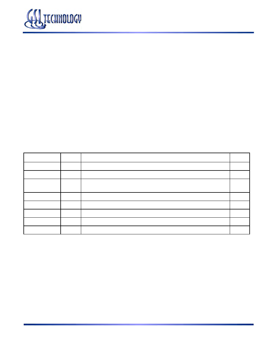
JTAG TAP Instruction Set Summary
Instruction
Code
Description
Notes
EXTEST
000
Places the Boundary Scan Register between TDI and TDO.
1
IDCODE
001
Preloads ID Register and places it between TDI and TDO.
1, 2
SAMPLE-Z
010
Captures I/O ring contents. Places the Boundary Scan Register between TDI and TDO.
Forces all RAM output drivers to High-Z.
1
GSI
011
GSI private instruction.
1
SAMPLE/PRELOAD
100
Captures I/O ring contents. Places the Boundary Scan Register between TDI and TDO.
1
GSI
101
GSI private instruction.
1
GSI
110
GSI private instruction.
1
BYPASS
111
Places Bypass Register between TDI and TDO.
1
Notes:
1. Instruction codes expressed in binary, MSB on left, LSB on right.
2. Default instruction automatically loaded at power-up and in test-logic-reset state.
相關PDF資料 |
PDF描述 |
|---|---|
| GS8182S18BD-300I | 1M X 18 DDR SRAM, 0.45 ns, PBGA165 |
| GS8182T08GBD-167IT | 2M X 8 DDR SRAM, 0.5 ns, PBGA165 |
| GS82032AT-4I | 64K X 32 CACHE SRAM, 10 ns, PQFP100 |
| GS8342S36AE-200S | 1M X 36 DDR SRAM, 0.45 ns, PBGA165 |
| GS880Z18CT-250IVT | 512K X 18 ZBT SRAM, QFP100 |
相關代理商/技術參數(shù) |
參數(shù)描述 |
|---|---|
| GS8182S18D-250 | 制造商:GSI Technology 功能描述:SRAM SYNC DUAL 1.8V 18MBIT 1MX18 0.45NS 165FBGA - Trays |
| GS8182S18D-250I | 制造商:GSI Technology 功能描述:SRAM SYNC DUAL 1.8V 18MBIT 1MX18 0.45NS 165FPBGA - Trays |
| GS8182S36BD-167 | 制造商:GSI Technology 功能描述:512K X 36 (18 MEG) BURST OF 2 - Trays |
| GS8182S36BD-167I | 制造商:GSI Technology 功能描述:512K X 36 (18 MEG) BURST OF 2 - Trays |
| GS8182S36BD-200 | 制造商:GSI Technology 功能描述:512K X 36 (18 MEG) BURST OF 2 - Trays |
發(fā)布緊急采購,3分鐘左右您將得到回復。