- 您現在的位置:買賣IC網 > PDF目錄371772 > HC05J5AGRS 68HC(7)05J5A General Release Specification PDF資料下載
參數資料
| 型號: | HC05J5AGRS |
| 英文描述: | 68HC(7)05J5A General Release Specification |
| 中文描述: | 68HC(7)05J5A總發(fā)行規(guī)格 |
| 文件頁數: | 45/106頁 |
| 文件大小: | 1366K |
| 代理商: | HC05J5AGRS |
第1頁第2頁第3頁第4頁第5頁第6頁第7頁第8頁第9頁第10頁第11頁第12頁第13頁第14頁第15頁第16頁第17頁第18頁第19頁第20頁第21頁第22頁第23頁第24頁第25頁第26頁第27頁第28頁第29頁第30頁第31頁第32頁第33頁第34頁第35頁第36頁第37頁第38頁第39頁第40頁第41頁第42頁第43頁第44頁當前第45頁第46頁第47頁第48頁第49頁第50頁第51頁第52頁第53頁第54頁第55頁第56頁第57頁第58頁第59頁第60頁第61頁第62頁第63頁第64頁第65頁第66頁第67頁第68頁第69頁第70頁第71頁第72頁第73頁第74頁第75頁第76頁第77頁第78頁第79頁第80頁第81頁第82頁第83頁第84頁第85頁第86頁第87頁第88頁第89頁第90頁第91頁第92頁第93頁第94頁第95頁第96頁第97頁第98頁第99頁第100頁第101頁第102頁第103頁第104頁第105頁第106頁

July 16, 1999
GENERAL RELEASE SPECIFICATION
MC68HC05J5A
REV 2.1
INPUT/OUTPUT PORTS
MOTOROLA
7-1
SECTION 7
INPUT/OUTPUT PORTS
In the normal operating mode there are 14 usable bidirectional I/O lines arranged
as one 8-bit I/O port (Port A), and one 6-bit I/O port (Port B). The individual bits in
these ports are programmable as either inputs or outputs under software control
by the data direction registers (DDR’s). Also, if enabled by a single mask option all
Port A and Port B I/O pins may have individual software programmable pull-down
or pull-up devices. Also, PA4-PA7 and PB1-PB2 pins have high current sink capa-
bility; PA0-PA3 may function as additional IRQ interrupt input sources. Note that
both PA6 and PA7 pins have Schmitt trigger input for better noise immunity. V
IH
and V
IL
specified at 2.4V and 0.8V, respectively.
The four port pins, PB2-PB5 are only available on the 20-pin version of the device.
7.1
SLOW OUTPUT FALLING-EDGE TRANSITION
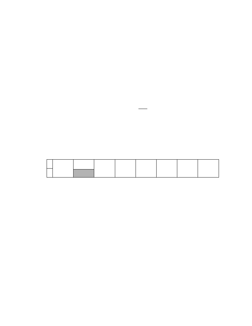
Figure 7-1. Port B Data Direction Register
SLOWE - Slow Transition Enable
The slow transition feature is controlled by the SLOWE bit of DDRB (Port B
Data Direction Register).
1 =
Enables the slow falling-edge output transition feature on the four I/
O lines: PA6, PA7, PB1, and PB2. If the pin is configured as an
output pin.
0 =
Disables slow falling-edge output transition feature on the four I/O
lines: PA6, PA7, PB1, and PB2. Default value of SLOWE bit is
cleared.
7.2
PORT A
Port A is a 8-bit bidirectional port which shares five of its pins with the IRQ inter-
rupt system as shown in
Figure 7-2
. Note that both PA6 and PA7 pins have
Schmitt trigger input for better noise immunity. Only the PA6 and PA7 pins are
open-drained type with slow output transition feature.
0
DDRB0
DDRB
$0005
0
7
W
R
0
0
0
0
0
0
0
reset
6
5
4
3
2
1
0
SLOWE
DDRB1
DDRB2
DDRB3
DDRB4
DDRB5
F
Freescale Semiconductor, Inc.
For More Information On This Product,
Go to: www.freescale.com
n
.
相關PDF資料 |
PDF描述 |
|---|---|
| HC05J5GRS | 68HC05J5 General Release Specification |
| HC05JB3GRS | 68HC05JB3 and 68HC705JB3 General Release Specification |
| HC05JB4GRS | 68HC(7)05JB4 General Release Specification |
| HC05JJ6GRS | 68HC05JJ6 and 68HC05JP6 General Release Specification |
| HC05K3GRS | 68HC05K3 General Release Specification |
相關代理商/技術參數 |
參數描述 |
|---|---|
| HC05J5GRS | 制造商:未知廠家 制造商全稱:未知廠家 功能描述:68HC05J5 General Release Specification |
| HC05JB3GRS | 制造商:未知廠家 制造商全稱:未知廠家 功能描述:68HC05JB3 and 68HC705JB3 General Release Specification |
| HC05JB4GRS | 制造商:未知廠家 制造商全稱:未知廠家 功能描述:68HC(7)05JB4 General Release Specification |
| HC05JJ6GRS | 制造商:未知廠家 制造商全稱:未知廠家 功能描述:68HC05JJ6 and 68HC05JP6 General Release Specification |
| HC05K3GRS | 制造商:未知廠家 制造商全稱:未知廠家 功能描述:68HC05K3 General Release Specification |
發(fā)布緊急采購,3分鐘左右您將得到回復。