- 您現(xiàn)在的位置:買賣IC網(wǎng) > PDF目錄1923 > HSP43220JC-33Z (Intersil)IC DECIMATING DGTL FILTER 84PLCC PDF資料下載
參數(shù)資料
| 型號: | HSP43220JC-33Z |
| 廠商: | Intersil |
| 文件頁數(shù): | 10/21頁 |
| 文件大?。?/td> | 0K |
| 描述: | IC DECIMATING DGTL FILTER 84PLCC |
| 標(biāo)準(zhǔn)包裝: | 15 |
| 濾波器類型: | 數(shù)字 |
| 濾波器數(shù): | 4 |
| 電源電壓: | 4.75 V ~ 5.25 V |
| 安裝類型: | 表面貼裝 |
| 封裝/外殼: | 84-LCC(J 形引線) |
| 供應(yīng)商設(shè)備封裝: | 84-PLCC(29.21x29.21) |
| 包裝: | 管件 |

18
FN2486.10
October 10, 2008
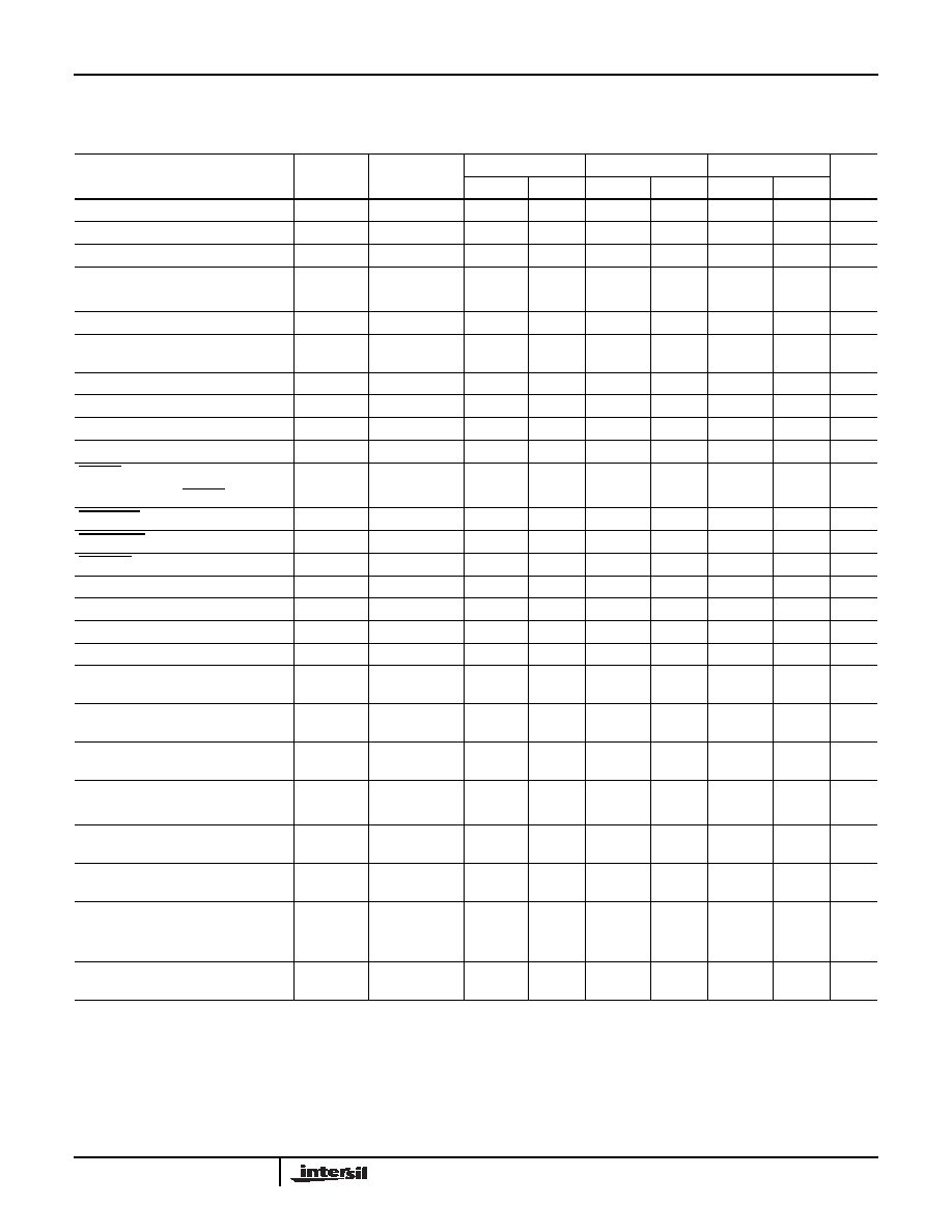
AC Electrical Specifications
tested at +25°C, unless otherwise specified. Temperature limits established by characterization and are
not production tested.
PARAMETER
SYMBOL
NOTES
-15
-25
-33
UNITS
MIN
MAX
MIN
MAX
MIN
MAX
Input Clock Frequency
FCK
0
15
0
25.6
0
33
MHz
FIR Clock Frequency
FFIR
0
15
0
25.6
0
33
MHz
Input Clock Period
tCK
66
-
39
-
30
-
ns
FIR Clock Period
tFIR
66
-
39
-
30
-
ns
Clock Pulse Width Low
tSPWL
26
-
16
-
13
-
ns
Clock Pulse Width High
tSPWH
26
-
16
-
13
-
ns
Clock Skew Between FIR_CK
and CK_IN
tSK
0
tFIR - 25
0
tFIR - 15
0
tFIR - 15
ns
CK_IN Pulse Width Low
tCH1L
(Notes 5, 8)
29
-
19
-
19
-
ns
CK_IN Pulse Width High
tCH1H
(Notes 5, 8)
29
-
19
-
19
-
ns
CK_IN Setup to FIR_CK
tCIS
(Notes 5, 8)
27
-
17
-
17
-
ns
CK_IN Hold from FIR_CK
tCIH
(Notes 5, 8)
2
-
2
-
2
-
ns
RESET Pulse Width Low
tRSPW
4tCK
-
4tCK
-
4tCK
-
ns
Recovery Time on RESET
tRTRS
8tCK
-
8tCK
-
8tCK
-
ns
ASTARTIN Pulse Width Low
tAST
tCK + 10
-
tCK + 10
-
tCK + 10
-
ns
STARTOUT Delay from CK_IN
tSTOD
-
35
-
20
-
18
ns
STARTIN Setup to CK_IN
tSTIC
25
-
15
-
10
-
ns
Setup Time on DATA_IN
tSET
20
-
15
-
14
-
ns
Hold Time on All inputs
tHOLD
0
-
0
-
0
-
ns
Write Pulse Width Low
tWL
26
-
15
-
12
-
ns
Write Pulse Width High
tWH
26
-
20
-
18
-
ns
Setup Time on Address Bus Before the
Rising Edge of Write
tSTADD
26
-
20
-
20
-
ns
Setup Time On-chip Select Before the
Rising Edge of Write
tSTCS
26
-
20
-
20
-
ns
Setup Time on Control Bus Before the
Rising Edge of Write
tSTCB
26
-
20
-
20
-
ns
DATA_RDY Pulse Width Low
tDRPWL
2tFIR - 20
-
2tFIR - 10
-
2tFIR - 10
-
ns
DATA_OUT Delay Relative to FIR_CK
tFIRDV
-
50
-
35
-
28
ns
DATA RDY Valid Delay Relative
to FIR_CK
tFIRDR
-
35
-
25
-
20
ns
DATA_OUT Delay Relative to
OUT_SELH
tOUT
-
25
-
20
-
20
ns
Output Enable to Data Out Valid
tOEV
(Note 6)
-
15
-
15
-
15
ns
Output Disable to Data Out
Three-State
tOEZ
(Note 5)
-
15
-
15
-
15
ns
Output Rise, Output Fall Times
tr, tf
from 0.8V to
2V, (Note 5)
-
8
-
8
-
6
ns
NOTES:
5. Controlled by design or process parameters and not directly tested. Characterized upon initial design and after major process and/or design
changes.
6. Transition is measured at ±200mV from steady state voltage with loading as specified in test load circuit with and CL = 40pF.
7. AC Testing is performed as follows: Input levels (CLK Input) 4.0V and 0V, Input levels (all other Inputs) 0V and 3.0V, Timing reference levels
(CLK) = 2.0V, (Others) = 1.5V, Output load per test load circuit and CL = 40pF.
8. Applies only when H_BYP = 1 or H_DRATE = 0.
HSP43220
相關(guān)PDF資料 |
PDF描述 |
|---|---|
| IA188EM-PTQ100I-R-03 | IC MCU 8/16BIT 40MHZ 100TQFP |
| IA188ES-PTQ100I-R-03 | IC MCU 8/16BIT 40MHZ 100TQFP |
| IA6805E2PLC44IR0 | IC MCU 8BIT 5MHZ 44PLCC |
| IA82050-PDW28I-R-01 | IC ASYNCHRONOUS SERIAL CTRL |
| IA82510-PDW28I-R-01 | IC ASYNCHRONOUS SERIAL CTRL |
相關(guān)代理商/技術(shù)參數(shù) |
參數(shù)描述 |
|---|---|
| HSP43220TM-15 | 制造商:未知廠家 制造商全稱:未知廠家 功能描述:Digital Filter |
| HSP43220TM-25 | 制造商:未知廠家 制造商全稱:未知廠家 功能描述:Digital Filter |
| HSP43220VC-25 | 制造商:Rochester Electronics LLC 功能描述:- Bulk 制造商:Harris Corporation 功能描述: |
| HSP43220VC-33 | 制造商:Rochester Electronics LLC 功能描述:- Bulk |
| HSP43481 | 制造商:INTERSIL 制造商全稱:Intersil Corporation 功能描述:Digital Filter |
發(fā)布緊急采購,3分鐘左右您將得到回復(fù)。