- 您現(xiàn)在的位置:買賣IC網(wǎng) > PDF目錄358798 > LH540215 (Sharp Corporation) 512 x 18 / 1024 x 18 Synchronous FIFO PDF資料下載
參數(shù)資料
| 型號: | LH540215 |
| 廠商: | Sharp Corporation |
| 英文描述: | 512 x 18 / 1024 x 18 Synchronous FIFO |
| 中文描述: | 512 ×一千〇二十四分之一十八× 18同步FIFO |
| 文件頁數(shù): | 10/48頁 |
| 文件大小: | 423K |
| 代理商: | LH540215 |
第1頁第2頁第3頁第4頁第5頁第6頁第7頁第8頁第9頁當前第10頁第11頁第12頁第13頁第14頁第15頁第16頁第17頁第18頁第19頁第20頁第21頁第22頁第23頁第24頁第25頁第26頁第27頁第28頁第29頁第30頁第31頁第32頁第33頁第34頁第35頁第36頁第37頁第38頁第39頁第40頁第41頁第42頁第43頁第44頁第45頁第46頁第47頁第48頁

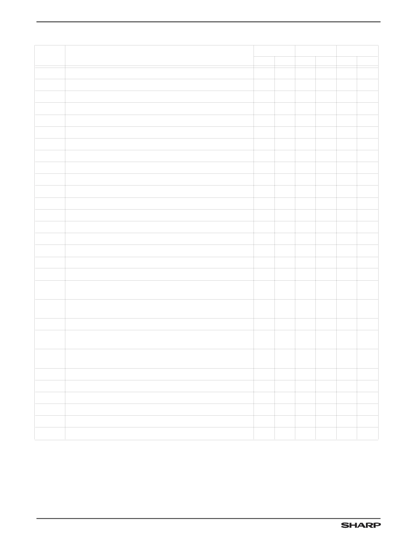
AC ELECTRICAL CHARACTERISTICS
SYMBOL
PARAMETER
–20
–25
-35
MIN.
MAX.
MIN.
MAX.
MIN.
MAX.
f
CC
Clock Cycle Frequency
50
40
28.6
t
A
Data Access Time
2
12
3
15
3
20
t
CLK
Clock Cycle Time
20
25
35
t
CLKH
Clock HIGH Time
8
10
14
t
CLKL
Clock LOW Time
8
10
14
t
DS
Data Setup Time
5
6
7
t
DH
Data Hold Time
2
2
2
t
ENS
Enable Setup Time
5
6
7
t
ENH
Enable Hold Time
Reset Pulse Width
1
2
2
2
t
RS
20
25
35
t
RSS
Reset Setup Time
2
Reset Recovery Time
2
12
15
20
t
RSR
12
15
20
t
RSF
Reset to Flag and Output Time
Output Enable to Output in Low-Z
2
30
35
40
t
OLZ
0
0
0
t
OE
Output Enable to Output Valid
Output Enable to Output in High-Z
2
9
12
15
t
OHZ
1
9
1
12
1
15
t
WFF
Write Clock to Full Flag
12
15
20
t
REF
Read Clock to Empty Flag
12
15
20
t
PAF
Clock to Programmable Almost-Full Flag (IDT-Compatible Operating
Mode)
14
17
23
t
PAE
Clock to Programmable Almost-Empty Flag (IDT-Compatible
Operating Mode)
14
17
23
t
HF
Clock to Half-Full Flag (IDT-Compatible Operating Mode)
14
17
23
t
PAFS
Clock to Programmable Almost-Full Flag
(Enhanced Operating Mode)
14
17
23
t
PAES
Clock to Programmable Almost-Empty Flag
(Enhanced Operating Mode)
14
17
23
t
HFS
Clock to Half-Full Flag (Enhanced Operating Mode)
14
17
23
t
XO
Clock to Expansion-Out
12
15
20
t
XI
Expansion-In Pulse Width
7
9
13
t
XIS
Expansion-In Setup Time
Skew Time Between Read Clock and Write Clock for Full Flag
3
Skew Time Between Write Clock and Read Clock for Empty Flag
4
7
9
14
t
SKEW1
9
11
16
t
SKEW2
9
11
16
NOTES:
1.
Pulse widths less than the stated minimum values may cause incorrect operation.
2.
Values are guaranteed by design; not currently tested.
3.
These times also apply to the Programmable-Almost-Full and Half-Full flags when they are synchronized to WCLK.
4.
These times also apply to the Half-Full and Programmable-Almost-Empty flags when they are synchronized to RCLK.
BOLD ITALIC = Enhanced Operating Mode
LH540215/25
512 x 18/1024 x 18 Synchronous FIFO
10
相關(guān)PDF資料 |
PDF描述 |
|---|---|
| LH540235 | 2048 x 18 / 4096 x 18 Synchronous FIFOs |
| LH5420 | 256 x 36 x 2 Bidirectional FIFO |
| LH5424-S | 5 mm T1 3/4 LED, Non Diffused Super-Bright, Hyper-Red GaAIAs-LED |
| LH5424-QT | 5 mm T1 3/4 LED, Non Diffused Super-Bright, Hyper-Red GaAIAs-LED |
| LH5424-T | 5 mm T1 3/4 LED, Non Diffused Super-Bright, Hyper-Red GaAIAs-LED |
相關(guān)代理商/技術(shù)參數(shù) |
參數(shù)描述 |
|---|---|
| LH540215U-15 | 制造商:未知廠家 制造商全稱:未知廠家 功能描述:x18 Synchronous FIFO |
| LH540215U-20 | 制造商:未知廠家 制造商全稱:未知廠家 功能描述:x18 Synchronous FIFO |
| LH540215U-25 | 制造商:未知廠家 制造商全稱:未知廠家 功能描述:x18 Synchronous FIFO |
| LH540215U-35 | 制造商:未知廠家 制造商全稱:未知廠家 功能描述:x18 Synchronous FIFO |
| LH540215U-50 | 制造商:未知廠家 制造商全稱:未知廠家 功能描述:x18 Synchronous FIFO |
發(fā)布緊急采購,3分鐘左右您將得到回復(fù)。