- 您現(xiàn)在的位置:買賣IC網(wǎng) > PDF目錄358798 > LH540215 (Sharp Corporation) 512 x 18 / 1024 x 18 Synchronous FIFO PDF資料下載
參數(shù)資料
| 型號: | LH540215 |
| 廠商: | Sharp Corporation |
| 英文描述: | 512 x 18 / 1024 x 18 Synchronous FIFO |
| 中文描述: | 512 ×一千〇二十四分之一十八× 18同步FIFO |
| 文件頁數(shù): | 36/48頁 |
| 文件大小: | 423K |
| 代理商: | LH540215 |
第1頁第2頁第3頁第4頁第5頁第6頁第7頁第8頁第9頁第10頁第11頁第12頁第13頁第14頁第15頁第16頁第17頁第18頁第19頁第20頁第21頁第22頁第23頁第24頁第25頁第26頁第27頁第28頁第29頁第30頁第31頁第32頁第33頁第34頁第35頁當(dāng)前第36頁第37頁第38頁第39頁第40頁第41頁第42頁第43頁第44頁第45頁第46頁第47頁第48頁
Q [17:0]
RCLK
FL/RT
FF
PAF
HF
PAE
EF
REN
1
540215-28
D
R1
t
ENS
t
RSF
D
RT12
D
RT2
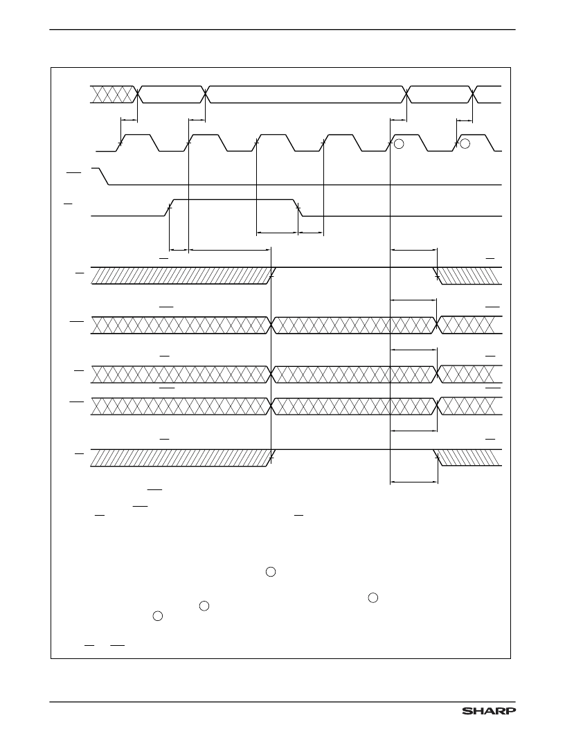
NOTES:
1. It is not necessary for REN to be LOW for the device to recognize a retransmit request.
2. In order to actually read data words from the memory arrary, in IDT-Compatible
Operating Mode, REN = LOW;
in Enhanced Operating Mode, also REN
= HIGH
(and OE = LOW, if Control Register bit 05 = HIGH).
In any case, LD = HIGH.
3. D
is the data item in physical location zero of the FIFO memory array.
4. The asynchronous intermediate flags (corresponding to LOW Control-Register bits) will
show correct status three RCLK cycles after a retransmit operation, as is shown above.
(RT
, in the above RCLK waveform.)
5. The intermediate flags which have been synchronized to RCLK, by setting the appropriate
Control-Register bits to HIGH will show correct status after B
retransmit operation. (RT
, in the above RCLK waveform.)
6. The intermediate flags which have been synchronized to WCLK, by setting the appropriate
Control-Register bits HIGH, will show correct status on the second WCLK rising edge after A
assuming that t
was satisfied at A
WCLK rising edge after A
7. Immediately after a reset operation, before any write operations have taken place, a retransmit
operation is a 'no-op', and does not change the state of any FIFO registers or flags.
8. In the special case that the FIFO memory array contains
only one
valid data item, the status
of HF and PAF should be ignored on a retransmit.
t
ENS
t
ENH
D
R2
t
A
t
A
t
PAF
R
1
R
2
RT
1
RT
2
RT
3
RT
4
t
WFF
t
HF
t
PAE
t
REF
NEW VALID FF
NEW VALID PAF
NEW VALID HF
NEW VALID PAE
NEW VALID EF
UNKNOWN
UNKNOWN
UNKNOWN
PREVIOUS VALID FF
PREVIOUS VALID PAF
PREVIOUS VALID HF
PREVIOUS VALID PAE
PREVIOUS VALID EF
A
B
t
A
t
A
Figure 21. Retransmit Timing
TIMING DIAGRAMS (cont’d)
LH540215/25
512 x 18/1024 x 18 Synchronous FIFO
36
相關(guān)PDF資料 |
PDF描述 |
|---|---|
| LH540235 | 2048 x 18 / 4096 x 18 Synchronous FIFOs |
| LH5420 | 256 x 36 x 2 Bidirectional FIFO |
| LH5424-S | 5 mm T1 3/4 LED, Non Diffused Super-Bright, Hyper-Red GaAIAs-LED |
| LH5424-QT | 5 mm T1 3/4 LED, Non Diffused Super-Bright, Hyper-Red GaAIAs-LED |
| LH5424-T | 5 mm T1 3/4 LED, Non Diffused Super-Bright, Hyper-Red GaAIAs-LED |
相關(guān)代理商/技術(shù)參數(shù) |
參數(shù)描述 |
|---|---|
| LH540215U-15 | 制造商:未知廠家 制造商全稱:未知廠家 功能描述:x18 Synchronous FIFO |
| LH540215U-20 | 制造商:未知廠家 制造商全稱:未知廠家 功能描述:x18 Synchronous FIFO |
| LH540215U-25 | 制造商:未知廠家 制造商全稱:未知廠家 功能描述:x18 Synchronous FIFO |
| LH540215U-35 | 制造商:未知廠家 制造商全稱:未知廠家 功能描述:x18 Synchronous FIFO |
| LH540215U-50 | 制造商:未知廠家 制造商全稱:未知廠家 功能描述:x18 Synchronous FIFO |
發(fā)布緊急采購,3分鐘左右您將得到回復(fù)。