- 您現(xiàn)在的位置:買賣IC網(wǎng) > PDF目錄367641 > P12C508 (Microchip Technology Inc.) 8-Pin, 8-Bit CMOS Microcontroller PDF資料下載
參數(shù)資料
| 型號: | P12C508 |
| 廠商: | Microchip Technology Inc. |
| 英文描述: | 8-Pin, 8-Bit CMOS Microcontroller |
| 中文描述: | 8引腳,8位CMOS微控制器 |
| 文件頁數(shù): | 11/84頁 |
| 文件大小: | 526K |
| 代理商: | P12C508 |
第1頁第2頁第3頁第4頁第5頁第6頁第7頁第8頁第9頁第10頁當(dāng)前第11頁第12頁第13頁第14頁第15頁第16頁第17頁第18頁第19頁第20頁第21頁第22頁第23頁第24頁第25頁第26頁第27頁第28頁第29頁第30頁第31頁第32頁第33頁第34頁第35頁第36頁第37頁第38頁第39頁第40頁第41頁第42頁第43頁第44頁第45頁第46頁第47頁第48頁第49頁第50頁第51頁第52頁第53頁第54頁第55頁第56頁第57頁第58頁第59頁第60頁第61頁第62頁第63頁第64頁第65頁第66頁第67頁第68頁第69頁第70頁第71頁第72頁第73頁第74頁第75頁第76頁第77頁第78頁第79頁第80頁第81頁第82頁第83頁第84頁

1996 Microchip Technology Inc.
Advance Information
DS40139A-page 11
PIC12C5XX
4.0
MEMORY ORGANIZATION
PIC12C5XX memory is organized into program mem-
ory and data memory. For devices with more than 512
bytes of program memory, a paging scheme is used.
Program memory pages are accessed using one STA-
TUS register bit. For the PIC12C509 with a data mem-
ory register file of more than 32 registers, a banking
scheme is used. Data memory banks are accessed
using the File Select Register (FSR).
4.1
Program Memory Organization
The PIC12C508 and PIC12C509 each have a 12-bit
Program Counter (PC) capable of addressing a 2K x
12 program memory space.
Only the first 512 x 12 (0000h-01FFh) for the
PIC12C508 and 1K x 12 (0000h-03FFh) for the
PIC12C509 are physically implemented. Refer to
Figure 4-1. Accessing a location above these
boundaries will cause a wrap-around within the first
512 x 12 space (PIC12C508) or 1K x 12 space
(PIC12C509). The reset vector is at 0000h. Location
01FFh (PIC12C508) or location 03FFh (PIC12C509)
contains the internal clock oscillator calibration value.
This value should never be overwritten.
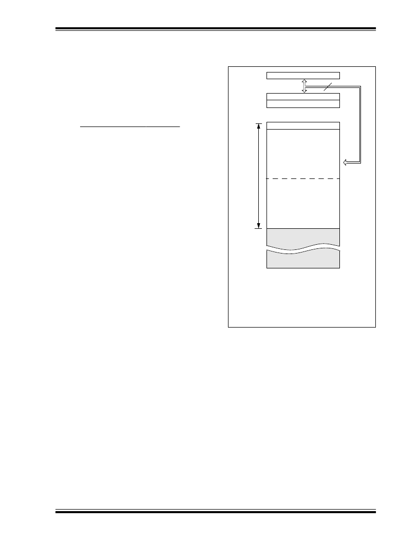
FIGURE 4-1:
PROGRAM MEMORY MAP
AND STACK FOR THE
PIC12C5XX
CALL, RETLW
PC<11:0>
Stack Level 1
Stack Level 2
U
S
12
0000h
7FFh
01FFh
0200h
On-chip Program
Memory
Reset Vector (note 1)
Note 1: Address 0000h becomes the effec-
tive reset vector. Location 01FFh
(PIC12C508) or location 03FFh
(PIC12C509) contains the MOVLW
XX clock calibration value.
512 Word (PIC12C508)
1024 Word (PIC12C509)
03FFh
0400h
On-chip Program
Memory
相關(guān)PDF資料 |
PDF描述 |
|---|---|
| P12 | ERSATZAKKU 12V |
| P1300SA | SIDACtor Device |
| P1100S | SIDACtor Device |
| P1100SCMC | solid state crowbar devices |
| P1100SD | solid state crowbar devices |
相關(guān)代理商/技術(shù)參數(shù) |
參數(shù)描述 |
|---|---|
| P12D | 制造商:Apex Tool Group 功能描述:12 IN. PRITCHEL |
| P12DM09001900F | 制造商:KEMET Corporation 功能描述: |
| P12DM22731900F | 制造商:KEMET Corporation 功能描述: |
| P12DRXX | 制造商:ATM 制造商全稱:ATM 功能描述:12.00 PHASESHIFTER OUTLINE - DIRECT READING DIAL |
| P12FAZ1 | 制造商:OMRON INDUSTRIAL AUTOMATION 功能描述:CPM1A-20CAR-A/32CAR-A Op. Man DX CODE ZA |
發(fā)布緊急采購,3分鐘左右您將得到回復(fù)。