- 您現(xiàn)在的位置:買賣IC網(wǎng) > PDF目錄378045 > PCI6420 (Texas Instruments, Inc.) Integrated 2-Slot PC Card & Dedicated Flash Media Controller PDF資料下載
參數(shù)資料
| 型號: | PCI6420 |
| 廠商: | Texas Instruments, Inc. |
| 英文描述: | Integrated 2-Slot PC Card & Dedicated Flash Media Controller |
| 中文描述: | 集成雙槽 PC 卡專用閃存介質(zhì)控制器 |
| 文件頁數(shù): | 139/160頁 |
| 文件大?。?/td> | 818K |
| 代理商: | PCI6420 |
第1頁第2頁第3頁第4頁第5頁第6頁第7頁第8頁第9頁第10頁第11頁第12頁第13頁第14頁第15頁第16頁第17頁第18頁第19頁第20頁第21頁第22頁第23頁第24頁第25頁第26頁第27頁第28頁第29頁第30頁第31頁第32頁第33頁第34頁第35頁第36頁第37頁第38頁第39頁第40頁第41頁第42頁第43頁第44頁第45頁第46頁第47頁第48頁第49頁第50頁第51頁第52頁第53頁第54頁第55頁第56頁第57頁第58頁第59頁第60頁第61頁第62頁第63頁第64頁第65頁第66頁第67頁第68頁第69頁第70頁第71頁第72頁第73頁第74頁第75頁第76頁第77頁第78頁第79頁第80頁第81頁第82頁第83頁第84頁第85頁第86頁第87頁第88頁第89頁第90頁第91頁第92頁第93頁第94頁第95頁第96頁第97頁第98頁第99頁第100頁第101頁第102頁第103頁第104頁第105頁第106頁第107頁第108頁第109頁第110頁第111頁第112頁第113頁第114頁第115頁第116頁第117頁第118頁第119頁第120頁第121頁第122頁第123頁第124頁第125頁第126頁第127頁第128頁第129頁第130頁第131頁第132頁第133頁第134頁第135頁第136頁第137頁第138頁當(dāng)前第139頁第140頁第141頁第142頁第143頁第144頁第145頁第146頁第147頁第148頁第149頁第150頁第151頁第152頁第153頁第154頁第155頁第156頁第157頁第158頁第159頁第160頁
7
–
5
7.5
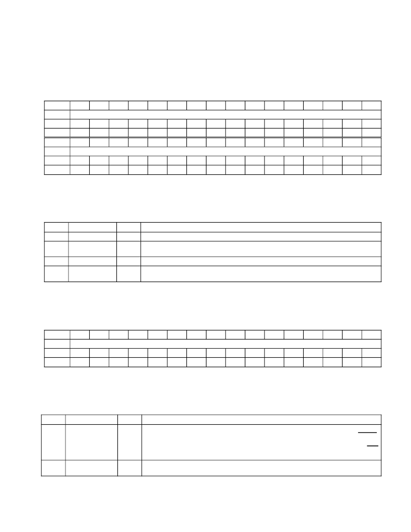
Class Code and Revision ID Register
The class code and revision ID register categorizes the base class, subclass, and programming interface of the
function. The base class is 01h, identifying the device as a mass storage controller. The subclass is 80h, identifying
the function as other mass storage controller, and the programming interface is 00h. Furthermore, the TI chip revision
is indicated in the least significant byte (00h). See Table 7
–
4 for a complete description of the register contents.
Bit
31
30
29
28
27
26
25
24
23
22
21
20
19
18
17
16
Name
Class code and revision ID
Type
R
R
R
R
R
R
R
R
R
R
R
R
R
R
R
R
Default
0
0
0
0
0
0
0
1
1
0
0
0
0
0
0
0
Bit
15
14
13
12
11
10
9
8
7
6
5
4
3
2
1
0
Name
Class code and revision ID
Type
R
R
R
R
R
R
R
R
R
R
R
R
R
R
R
R
Default
0
0
0
0
0
0
0
0
0
0
0
0
0
0
0
0
Register:
Offset:
Type:
Default:
Class code and revision ID
08h
Read-only
0180 0000h
Table 7
–
4. Class Code and Revision ID Register Description
BIT
FIELD NAME
TYPE
DESCRIPTION
31
–
24
BASECLASS
R
Base class. This field returns 01h when read, which classifies the function as a mass storage controller.
23
–
16
SUBCLASS
R
Subclass. This field returns 80h when read, which specifically classifies the function as other mass
storage controller.
Programming interface. This field returns 00h when read.
15
–
8
PGMIF
R
7
–
0
CHIPREV
R
Silicon revision. This field returns 00h when read, which indicates the silicon revision of the flash media
controller.
7.6
Latency Timer and Class Cache Line Size Register
The latency timer and class cache line size register is programmed by host BIOS to indicate system cache line size
and the latency timer associated with the flash media controller. See Table 7
–
5 for a complete description of the
register contents.
Bit
15
14
13
12
11
10
9
8
7
6
5
4
3
2
1
0
Name
Latency timer and class cache line size
Type
RW
RW
RW
RW
RW
RW
RW
RW
RW
RW
RW
RW
RW
RW
RW
RW
Default
0
0
0
0
0
0
0
0
0
0
0
0
0
0
0
0
Register:
Offset:
Type:
Default:
Latency timer and class cache line size
0Ch
Read/Write
0000h
Table 7
–
5. Latency Timer and Class Cache Line Size Register Description
BIT
FIELD NAME
TYPE
DESCRIPTION
15
–
8
LATENCY_TIMER
RW
PCI latency timer. The value in this register specifies the latency timer for the flash media controller,
in units of PCI clock cycles. When the flash media controller is a PCI bus initiator and asserts FRAME,
the latency timer begins counting from zero. If the latency timer expires before the flash media
transaction has terminated, then the flash media controller terminates the transaction when its GNT
is deasserted.
Cache line size. This value is used by the flash media controller during memory write and invalidate,
memory-read line, and memory-read multiple transactions.
7
–
0
CACHELINE_SZ
RW
相關(guān)PDF資料 |
PDF描述 |
|---|---|
| PCI6421 | DUAL/SINGLE SOCKET CARDBUS AND ULTRAMEDIA CONTROLLER |
| PCI6611 | DUAL/SINGLE SOCKET CARDBUS AND ULTRAMEDIA CONTROLLER |
| PCI6621 | DUAL/SINGLE SOCKET CARDBUS AND ULTRAMEDIA CONTROLLER |
| PCI6515 | SINGLE SOCKET CARDBUS CONTROLLER WITH DEDICATED SMART CARD SOCKET |
| PCI6515GHK | SINGLE SOCKET CARDBUS CONTROLLER WITH DEDICATED SMART CARD SOCKET |
相關(guān)代理商/技術(shù)參數(shù) |
參數(shù)描述 |
|---|---|
| PCI6420GHK | 功能描述:外圍驅(qū)動器與原件 - PCI Integrated 2-Slot PC Card & Flash Cntrl RoHS:否 制造商:PLX Technology 工作電源電壓: 最大工作溫度: 安裝風(fēng)格:SMD/SMT 封裝 / 箱體:FCBGA-1156 封裝:Tray |
| PCI6420ZHK | 功能描述:外圍驅(qū)動器與原件 - PCI Integrated 2-Slot PC Card & Flash Cntrl RoHS:否 制造商:PLX Technology 工作電源電壓: 最大工作溫度: 安裝風(fēng)格:SMD/SMT 封裝 / 箱體:FCBGA-1156 封裝:Tray |
| PCI6421 | 制造商:TI 制造商全稱:Texas Instruments 功能描述:DUAL/SINGLE SOCKET CARDBUS AND ULTRAMEDIA CONTROLLER |
| PCI6421GHK | 制造商:Texas Instruments 功能描述:DUAL/SGL SCKT CARDBUS AND ULTRAMEDIA CNTRLR W/ DEDICATED FLA - Trays |
| PCI6421ZHK | 制造商:Texas Instruments 功能描述:DUAL/SGL SCKT CARDBUS AND ULTRAMEDIA CNTRLR W/ DEDICATED FLA - Trays |
發(fā)布緊急采購,3分鐘左右您將得到回復(fù)。