- 您現(xiàn)在的位置:買賣IC網(wǎng) > PDF目錄378045 > PCI6420 (Texas Instruments, Inc.) Integrated 2-Slot PC Card & Dedicated Flash Media Controller PDF資料下載
參數(shù)資料
| 型號: | PCI6420 |
| 廠商: | Texas Instruments, Inc. |
| 英文描述: | Integrated 2-Slot PC Card & Dedicated Flash Media Controller |
| 中文描述: | 集成雙槽 PC 卡專用閃存介質(zhì)控制器 |
| 文件頁數(shù): | 47/160頁 |
| 文件大小: | 818K |
| 代理商: | PCI6420 |
第1頁第2頁第3頁第4頁第5頁第6頁第7頁第8頁第9頁第10頁第11頁第12頁第13頁第14頁第15頁第16頁第17頁第18頁第19頁第20頁第21頁第22頁第23頁第24頁第25頁第26頁第27頁第28頁第29頁第30頁第31頁第32頁第33頁第34頁第35頁第36頁第37頁第38頁第39頁第40頁第41頁第42頁第43頁第44頁第45頁第46頁當(dāng)前第47頁第48頁第49頁第50頁第51頁第52頁第53頁第54頁第55頁第56頁第57頁第58頁第59頁第60頁第61頁第62頁第63頁第64頁第65頁第66頁第67頁第68頁第69頁第70頁第71頁第72頁第73頁第74頁第75頁第76頁第77頁第78頁第79頁第80頁第81頁第82頁第83頁第84頁第85頁第86頁第87頁第88頁第89頁第90頁第91頁第92頁第93頁第94頁第95頁第96頁第97頁第98頁第99頁第100頁第101頁第102頁第103頁第104頁第105頁第106頁第107頁第108頁第109頁第110頁第111頁第112頁第113頁第114頁第115頁第116頁第117頁第118頁第119頁第120頁第121頁第122頁第123頁第124頁第125頁第126頁第127頁第128頁第129頁第130頁第131頁第132頁第133頁第134頁第135頁第136頁第137頁第138頁第139頁第140頁第141頁第142頁第143頁第144頁第145頁第146頁第147頁第148頁第149頁第150頁第151頁第152頁第153頁第154頁第155頁第156頁第157頁第158頁第159頁第160頁
3
–
9
3.6.6
Internal Ring Oscillator
The internal ring oscillator provides an internal clock source for the PCI6x20 device so that neither the PCI clock nor
an external clock is required in order for the PCI6x20 device to power down a socket or interrogate a PC Card. This
internal oscillator, operating nominally at 16 kHz, is always enabled.
3.6.7
Integrated Pullup Resistors for PC Card Interface
The
PC Card Standard
requires pullup resistors on various terminals to support both CardBus and 16-bit PC Card
configurations. The PCI6x20 device has integrated all of these pullup resistors and requires no additional external
components. The I/O buffer on the BVD1(STSCHG)/CSTSCHG terminal has the capability to switch to an internal
pullup resistor when a 16-bit PC Card is inserted, or switch to an internal pulldown resistor when a CardBus card is
inserted. This prevents inadvertent CSTSCHG events. The pullup resistor requirements for the various UltraMedia
interfaces are either included in the UltraMedia cards (or the UltraMedia adapter) or are part of the existing PCMCIA
architecture. The PCI6x20 device does not require any additional components for UltraMedia support.
3.6.8
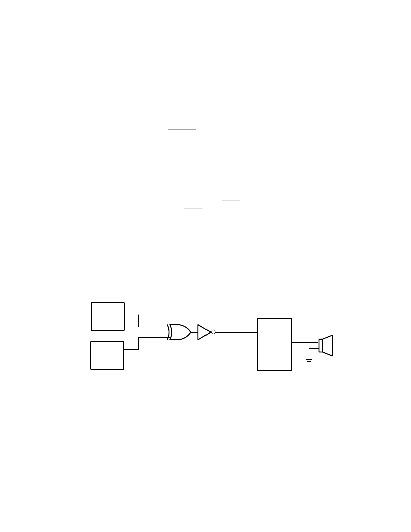
SPKROUT and CAUDPWM Usage
The SPKROUT terminal carries the digital audio signal from the PC Card to the system. When a 16-bit PC Card is
configured for I/O mode, the BVD2 terminal becomes the SPKR input terminal from the card. This terminal, in
CardBus applications, is referred to as CAUDIO. SPKR passes a TTL-level binary audio signal to the PCI6x20 device.
The CardBus CAUDIO signal also can pass a single-amplitude binary waveform as well as a PWM signal. The binary
audio signal from each PC Card sockets is enabled by bit 1 (SPKROUTEN) of the card control register (PCI offset
91h, see Section 4.38).
Older controllers support CAUDIO in binary or PWM mode, but use the same output terminal (SPKROUT). Some
audio chips may not support both modes on one terminal and may have a separate terminal for binary and PWM.
The PCI6x20 implementation includes a signal for PWM, CAUDPWM, which can be routed to an MFUNC terminal.
Bit 2 (AUD2MUX), located in the card control register, is programmed to route a CardBus CAUDIO PWM terminal
to CAUDPWM. See Section 4.36,
Multifunction Routing Register
, for details on configuring the MFUNC terminals.
Figure 3
–
4 illustrates the SPKROUT connection.
Speaker
Subsystem
BINARY_SPKR
System
Core Logic
PCI6x20
CAUDPWM
SPKROUT
PWM_SPKR
Figure 3
–
4. SPKROUT Connection to Speaker Driver
3.6.9
LED Socket Activity Indicators
The socket activity LEDs are provided to indicate when a PC Card is being accessed. The LEDA1 and LEDA2 signals
can be routed to the multifunction terminals. When configured for LED output, these terminals output an active high
signal to indicate socket activity. LEDA1 indicates socket A (card A) activity, and LEDA2 indicates socket B (card B)
activity. The LED_SKT output indicates socket activity to either socket A or socket B. See Section 4.36,
Multifunction
Routing Status Register
,
for details on configuring the multifunction terminals.
The active-high LED signal is driven for 64 ms. When the LED is not being driven high, it is driven to a low state. Either
of the two circuits shown in Figure 3
–
5 can be implemented to provide LED signaling, and the board designer must
implement the circuit that best fits the application.
相關(guān)PDF資料 |
PDF描述 |
|---|---|
| PCI6421 | DUAL/SINGLE SOCKET CARDBUS AND ULTRAMEDIA CONTROLLER |
| PCI6611 | DUAL/SINGLE SOCKET CARDBUS AND ULTRAMEDIA CONTROLLER |
| PCI6621 | DUAL/SINGLE SOCKET CARDBUS AND ULTRAMEDIA CONTROLLER |
| PCI6515 | SINGLE SOCKET CARDBUS CONTROLLER WITH DEDICATED SMART CARD SOCKET |
| PCI6515GHK | SINGLE SOCKET CARDBUS CONTROLLER WITH DEDICATED SMART CARD SOCKET |
相關(guān)代理商/技術(shù)參數(shù) |
參數(shù)描述 |
|---|---|
| PCI6420GHK | 功能描述:外圍驅(qū)動器與原件 - PCI Integrated 2-Slot PC Card & Flash Cntrl RoHS:否 制造商:PLX Technology 工作電源電壓: 最大工作溫度: 安裝風(fēng)格:SMD/SMT 封裝 / 箱體:FCBGA-1156 封裝:Tray |
| PCI6420ZHK | 功能描述:外圍驅(qū)動器與原件 - PCI Integrated 2-Slot PC Card & Flash Cntrl RoHS:否 制造商:PLX Technology 工作電源電壓: 最大工作溫度: 安裝風(fēng)格:SMD/SMT 封裝 / 箱體:FCBGA-1156 封裝:Tray |
| PCI6421 | 制造商:TI 制造商全稱:Texas Instruments 功能描述:DUAL/SINGLE SOCKET CARDBUS AND ULTRAMEDIA CONTROLLER |
| PCI6421GHK | 制造商:Texas Instruments 功能描述:DUAL/SGL SCKT CARDBUS AND ULTRAMEDIA CNTRLR W/ DEDICATED FLA - Trays |
| PCI6421ZHK | 制造商:Texas Instruments 功能描述:DUAL/SGL SCKT CARDBUS AND ULTRAMEDIA CNTRLR W/ DEDICATED FLA - Trays |
發(fā)布緊急采購,3分鐘左右您將得到回復(fù)。