- 您現(xiàn)在的位置:買賣IC網(wǎng) > PDF目錄369953 > PCT789T-A PCI HSP56 World MicroModem/PCT303DW/PCT1789W PDF資料下載
參數(shù)資料
| 型號: | PCT789T-A |
| 英文描述: | PCI HSP56 World MicroModem/PCT303DW/PCT1789W |
| 中文描述: | 世界MicroModem/PCT303DW/PCT1789W的PCI HSP56 |
| 文件頁數(shù): | 17/70頁 |
| 文件大?。?/td> | 872K |
| 代理商: | PCT789T-A |
第1頁第2頁第3頁第4頁第5頁第6頁第7頁第8頁第9頁第10頁第11頁第12頁第13頁第14頁第15頁第16頁當(dāng)前第17頁第18頁第19頁第20頁第21頁第22頁第23頁第24頁第25頁第26頁第27頁第28頁第29頁第30頁第31頁第32頁第33頁第34頁第35頁第36頁第37頁第38頁第39頁第40頁第41頁第42頁第43頁第44頁第45頁第46頁第47頁第48頁第49頁第50頁第51頁第52頁第53頁第54頁第55頁第56頁第57頁第58頁第59頁第60頁第61頁第62頁第63頁第64頁第65頁第66頁第67頁第68頁第69頁第70頁

PC-TEL, Inc.
17
1789W0DOCDAT06A-0299
PCT1789W DATA SHEET
PCT303DW F
UNCTIONAL
D
ESCRIPTION
!
PRELIMINARY
PRELIMINARY
PCT303DW F
UNCTIONAL
D
ESCRIPTION
The PCT303DW is an integrated direct access
arrangement (DAA) that provides a programmable line
interface
to
meet
international
requirements.
The
device
Laboratories’ proprietary ISOLink
technology which
offers the highest level of integration by replacing an
analog front end (AFE), an isolation transformer, relays,
opto-isolators, and a 2–4-wire hybrid with two 16-pin
small outline packages (SOIC). The chipset can be fully
programmed to meet international requirements, and
the device is compliant with FCC, NET4, CTR21, JATE,
and country-specific PTT specifications. In addition, the
PCT303DW has been designed to meet the most
stringent world-wide requirements for out-of-band
energy, billing-tone immunity, lightning surges, and
safety requirements.
telephone-line
implements
Silicon
The PCT303DW solution needs only a few low-cost
discrete components to achieve global compliance. See
Figure 2 on page 6 for a typical application circuit.
Isolation Barrier
The PCT303DW achieves an isolation barrier through a
low-cost, high-voltage capacitor in conjunction with
ISOLink
signal
processing
techniques eliminate any signal degradation due to
capacitor mismatches, common mode interference, or
noise coupling. As shown in Figure 2, the C1, C2, and
C4 capacitors isolate the PCT303D (DSP side) from the
PCT303W (line side). All transmit, receive, control, and
caller ID data are communicated through this barrier.
techniques.
These
The Isolation Pass is disabled by default. To enable it,
the PDL bit in register 6 must be cleared. No
communication between the PCT303D and PCT303W
can occur until this bit is cleared. The clock generator
must be programmed to an acceptable sample rate prior
to clearing the PDL bit.
AC Termination
The PCT303DW supports international AC Termination
requirements with two selectable impedances, one real
and one complex. Mode 0 is a nominal 600-ohm
termination that supports the FCC 68 requirement in
addition to the requirement of many European countries.
Mode 1 is a complex impedance as dictated by
countries such as the UK and Germany, and also
specified by CTR21. This complex impedance is set by
circuitry internal to the PCT303DW as well as the
external components connected to REXT2.
DC Termination
The PCT303DW has four programmable modes related
to DC termination. Two bits in register 16 (DCT1, DCT0)
set the DC characteristics. While the modes are
designed to support the extreme conditions in various
countries, the user can determine if a line in a given
country can support a mode with a higher transmit
power level and switch to the appropriate mode. This
decision will depend on the amount of loop current
available on the line.
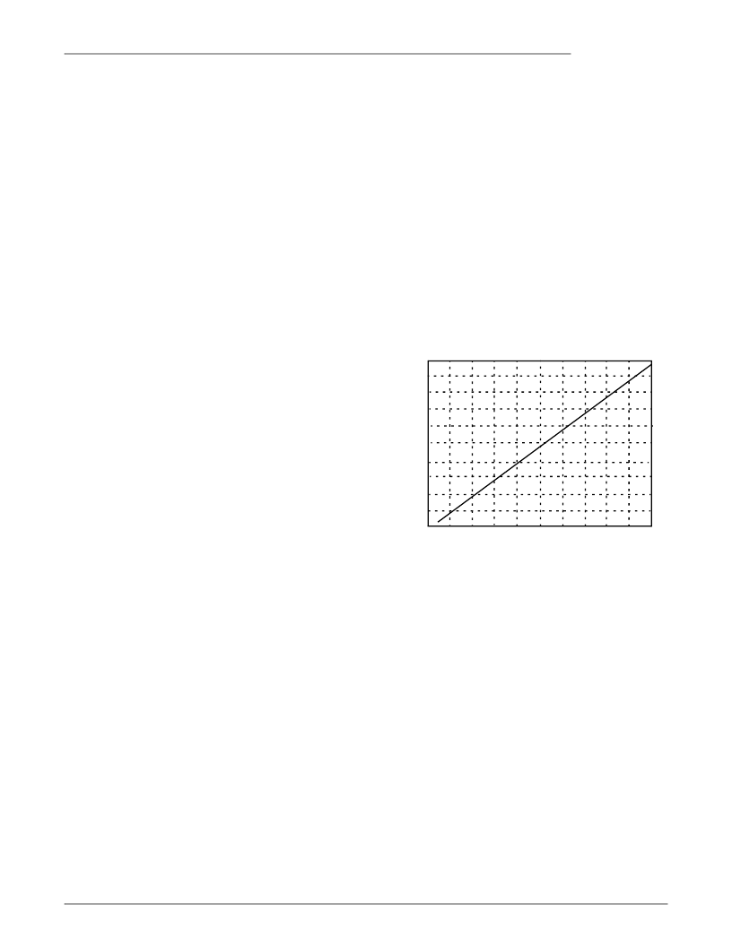
Mode 1 (0,1) is a low-voltage mode with no current
limiting; it supports transmit signals up to –2.71 dBm.
The low voltage requirement is dictated by countries
such as Japan and Australia. See Figure 7.
Figure 7 Mode 1 I/V Characteristics (0,1)
Mode 2 (1,0) is the default DC termination mode, with no
current limiting, providing a maximum transmit level of
–1 dBm at Tip and Ring. This mode meets FCC
requirements in addition to the requirements of many
European countries. Figure 8 shows the I/V
characteristics of mode 2.
10.5
10
9.5
9
8.5
8
7.5
7
6.5
.01 .02 .03 .04 .05 .06 .07 .08 .09 .1
Loop Current (A)
Mode 1
V
6
5.5
.11
相關(guān)PDF資料 |
PDF描述 |
|---|---|
| PCX-150 | 150A QUASI- CW LASER DIODE DRIVER/PULSED CURRENT SOURCE |
| PCX-6220 | 150A 40V QUASI-CW LASER DIODE DRIVER/PULSED CURRENT SOURCE |
| PCXO116 | Logic IC |
| PD-110A | CAP,CERM,TRIM,5mm,9-50pf, 200VDC COLOR GREEN,2 LEADS |
| PD-110B | CAP,CERM,TRIM,8mm,8.5-100pF, 250V,COLOR PURPLE |
相關(guān)代理商/技術(shù)參數(shù) |
參數(shù)描述 |
|---|---|
| PCT789T-C | 制造商:PCTEL 功能描述:PCI MODEM CHIP |
| PCT789T-C1 | 制造商:Rochester Electronics LLC 功能描述:- Bulk |
| PCT900 | 制造商:General Tools 功能描述:Combination Contact/Non-Contact Laser Tachometer 制造商:General Tools 功能描述:TACHOMETERMINI PHOTO |
| PCT-A | 制造商:Cooper Interconnect 功能描述: 制造商:Cooper Bussmann 功能描述: 制造商:COOPER BUSSMANN 功能描述:Fuse Holder 125V Pin Through Hole |
| PCTABLE | 制造商:Black Box Corporation 功能描述:PC / UTILITY TABLE 28"H X 36"W X 24"D |
發(fā)布緊急采購,3分鐘左右您將得到回復(fù)。