- 您現(xiàn)在的位置:買賣IC網(wǎng) > PDF目錄361304 > QR0001 PDF資料下載
參數(shù)資料
| 型號: | QR0001 |
| 文件頁數(shù): | 27/40頁 |
| 文件大小: | 440K |
| 代理商: | QR0001 |
第1頁第2頁第3頁第4頁第5頁第6頁第7頁第8頁第9頁第10頁第11頁第12頁第13頁第14頁第15頁第16頁第17頁第18頁第19頁第20頁第21頁第22頁第23頁第24頁第25頁第26頁當(dāng)前第27頁第28頁第29頁第30頁第31頁第32頁第33頁第34頁第35頁第36頁第37頁第38頁第39頁第40頁

10.0 QR0001 Operation Flow
(Continued)
QR0001 sends an additional voucher as soon as it identifies
that one packet is not going to be enough to transmit all the
data in the transmit pipeline.
No packet is sent until a ticket is received. This includes low
bandwidth packets.
QR0001 does not wait for data; therefore, packets could
vary in size.
The largest and most efficient packet is one formed by 1
head symbol and 20 payload symbols, 21 symbols in all.
Low Bandwidth packets are 1 head and 1 payload symbol.
The client interface must stop writing data at the transmit
port within 20 non-null symbols after TxOK negates. The
count is reset if TxOK asserts again.
10.4 Inside the Target Node
At the target node, if the receiving controller has space for
one packet in the Target FIFO, it will send a ticket immedi-
ately to the source node in response to a voucher. A
QR0001 Target FIFO has space for 3 normal packets and 6
low bandwidth packets; therefore, the controller can have
only 3 outstanding normal tickets and 6 outstanding low
bandwidth tickets. If all tickets have been given, the receiv-
ing QR0001 will queue incoming vouchers in one of two
special buffers, called Target Handler and LB Target Han-
dler. The Target Handler can store 30 vouchers and the LB
Target Handler can store 10 vouchers for low bandwidth
transmission.
At the target node, a new ticket is released as soon as a
packet has exited the Target FIFO to the Rx Resynchroniz-
er. This is determined internally by matching the tickets giv-
en and the tails exiting the target FIFO.
If the target node cannot return a ticket or store the voucher
to be handled later, it will return a voucher rejected to the
source node. (The Source will sink the voucher and the
node will then re-send the voucher after 100 clock cycles.)
10.5 Summary of Target Node Actions
The target FIFO can handle 3 normal packets and 6 low
bandwidth packets. Therefore, only 3 normal tickets and 6
LB tickets can be outstanding at one time.
QR0001 can store 30 normal vouchers and 10 LB vouchers
before returning a voucherDreject to the source node.
The Head Stripper will remove the head of all packets be-
fore entering the Target FIFO, unless there is a change in
stream (new head).
Data may arrive at the Rx Port on every tick of the clock
unless the client stops the flow through the RxSTALL input.
RxET can be used to monitor the kind of data entering the
receive pipeline up to 20 symbols before it appears at the
receive port. When the Rx pipeline is free flowing in the
unblocked pipe (RxSTALL is negated), RxET will indicate
the Type:
1. Three clock cycles early the symbols (RxS) in the pipe-
lined timing and
2. Two clock cycles early the symbols (RxS) in the non-
pipelined timing.
11.0 Board Considerations
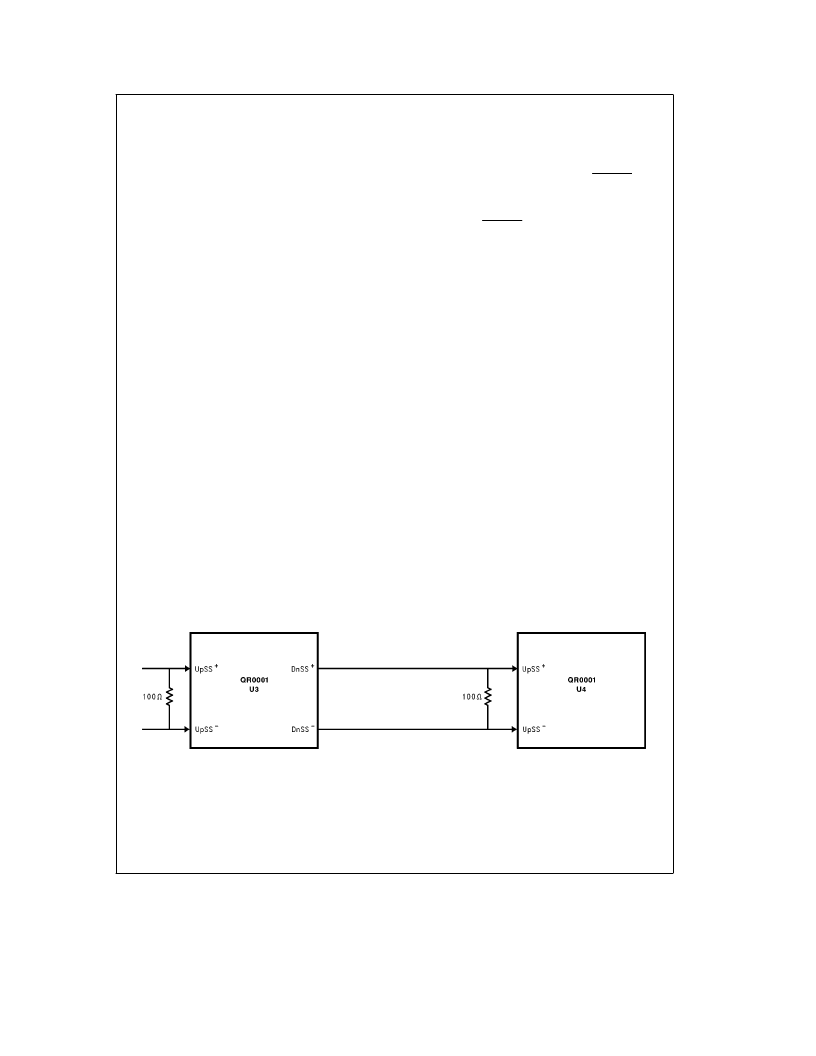
11.1 Upstream Port Signal Termination
The ring interface upstream port signals: UpSS
[
5:0
]
, and
UpCLK need external termination. The termination should
be a 100
X
resistor between the differential signal pair. The
resistor should be placed as close to the upstream port pins
as possible. Minimum parasitic inductance and capacitance
is desirable. Surface mount chip resistors with
g
1% toler-
ance are recommended. See Figure 11.1.
11.2 QuickRing Physical Layer Details
The QuickRing 180 MHz data signals dictate special care
for the physical layer design and layout. The use of LVDS
(Low Voltage Differential Signals) enables the very high fre-
quency operation. The LVDS also eases design because
the differential signals are forgiving to certain impedance
discontinuities in the signal path. If the discontinuities are at
the same electrical distance and have the same magnitude,
they will not distort the differential signal. Each single ended
signal may appear to have reflections, but if the differential
pair has the same minor reflections, then the differential
signal will not be affected. The skew between the pairs and
inside the pairs is a critical design criteria. These are the
basic guidelines for transporting the ring signals.
The skew between pairs and between single ended signals
inside a pair is critical. First, the skew between signal pairs.
The 350 MBaud signals only provide a bit width of about
TL/F/11928–26
FIGURE 11.1. Termination between the Differential Signal pair
27
相關(guān)PDF資料 |
PDF描述 |
|---|---|
| QR0610T30 | 128 x 128 pixel format, LED Backlight available |
| QRD0610T30 | 128 x 128 pixel format, LED or EL Backlight available |
| QRC0610T30 | 128 x 128 pixel format, LED or EL Backlight available |
| QRF0610T30 | 128 x 128 pixel format, LED or EL Backlight available |
| QR0620T30 | 128 x 128 pixel format, LED or EL Backlight available |
相關(guān)代理商/技術(shù)參數(shù) |
參數(shù)描述 |
|---|---|
| QR0610T30 | 制造商:POWEREX 制造商全稱:Powerex Power Semiconductors 功能描述:Fast Recovery Diode Module (100 Amp/600 Volts) |
| QR0620T30 | 制造商:POWEREX 制造商全稱:Powerex Power Semiconductors 功能描述:Fast Recovery Diode Module (200 Amp/600 Volts) |
| QR0630T30 | 制造商:POWEREX 制造商全稱:Powerex Power Semiconductors 功能描述:Fast Recovery Diode Module (300 Amp/600 Volts) |
| QR0640T30 | 制造商:POWEREX 制造商全稱:Powerex Power Semiconductors 功能描述:Fast Recovery Diode Module (400 Amp/600 Volts) |
| QR06A-2/106349 | 功能描述:BLWR CROSS FLOW 460X158MM 115VAC RoHS:是 類別:風(fēng)扇,熱管理 >> 風(fēng)扇 - AC 系列:QR06 其它有關(guān)文件:Declaration of Conformity 標(biāo)準(zhǔn)包裝:1 系列:- 氣流:- 軸承類型:- 風(fēng)扇類型:- 特點(diǎn):- 雜訊:- 功率(瓦特):- RPM:- 尺寸/尺寸:- 靜態(tài)壓力:- 端子:- 電壓 - 額定:- 重量:- 額定電流:- 預(yù)期壽命:- 工作溫度:- 電壓范圍:- 其它名稱:Q5464961 |
發(fā)布緊急采購,3分鐘左右您將得到回復(fù)。