- 您現(xiàn)在的位置:買(mǎi)賣(mài)IC網(wǎng) > PDF目錄373275 > RK80530KZ017512 MICROPROCESSOR|32-BIT|CMOS|PGA|370PIN|CERAMIC PDF資料下載
參數(shù)資料
| 型號(hào): | RK80530KZ017512 |
| 英文描述: | MICROPROCESSOR|32-BIT|CMOS|PGA|370PIN|CERAMIC |
| 中文描述: | 微處理器| 32位|的CMOS |美巡賽| 370PIN |陶瓷 |
| 文件頁(yè)數(shù): | 81/86頁(yè) |
| 文件大小: | 882K |
| 代理商: | RK80530KZ017512 |
第1頁(yè)第2頁(yè)第3頁(yè)第4頁(yè)第5頁(yè)第6頁(yè)第7頁(yè)第8頁(yè)第9頁(yè)第10頁(yè)第11頁(yè)第12頁(yè)第13頁(yè)第14頁(yè)第15頁(yè)第16頁(yè)第17頁(yè)第18頁(yè)第19頁(yè)第20頁(yè)第21頁(yè)第22頁(yè)第23頁(yè)第24頁(yè)第25頁(yè)第26頁(yè)第27頁(yè)第28頁(yè)第29頁(yè)第30頁(yè)第31頁(yè)第32頁(yè)第33頁(yè)第34頁(yè)第35頁(yè)第36頁(yè)第37頁(yè)第38頁(yè)第39頁(yè)第40頁(yè)第41頁(yè)第42頁(yè)第43頁(yè)第44頁(yè)第45頁(yè)第46頁(yè)第47頁(yè)第48頁(yè)第49頁(yè)第50頁(yè)第51頁(yè)第52頁(yè)第53頁(yè)第54頁(yè)第55頁(yè)第56頁(yè)第57頁(yè)第58頁(yè)第59頁(yè)第60頁(yè)第61頁(yè)第62頁(yè)第63頁(yè)第64頁(yè)第65頁(yè)第66頁(yè)第67頁(yè)第68頁(yè)第69頁(yè)第70頁(yè)第71頁(yè)第72頁(yè)第73頁(yè)第74頁(yè)第75頁(yè)第76頁(yè)第77頁(yè)第78頁(yè)第79頁(yè)第80頁(yè)當(dāng)前第81頁(yè)第82頁(yè)第83頁(yè)第84頁(yè)第85頁(yè)第86頁(yè)
Datasheet
81
Intel
Pentium
III Processor with 512KB L2 Cache at 1.13GHz to 1.40GHz
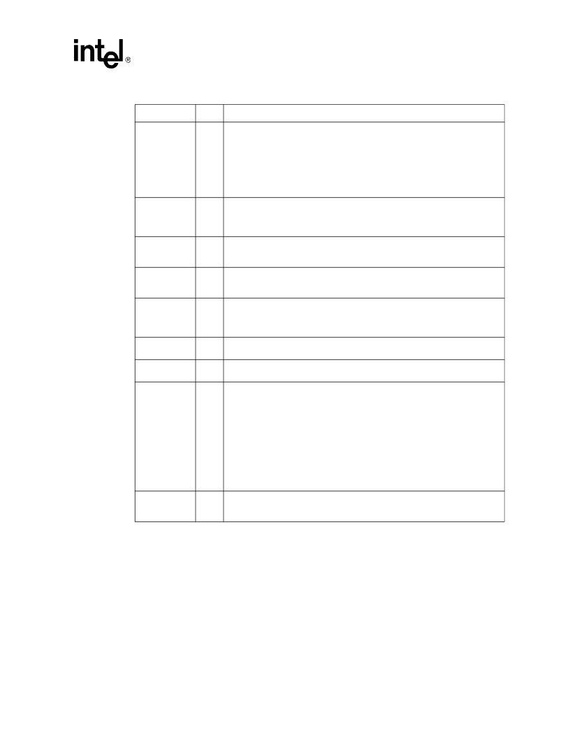
LOCK#
I/O
The LOCK# signal indicates to the system that a transaction must occur atomically.
This signal must connect the appropriate pins of all processor system bus agents.
For a locked sequence of transactions, LOCK# is asserted from the beginning of
the first transaction end of the last transaction.
When the priority agent asserts BPRI# to arbitrate for ownership of the processor
system bus, it will wait until it observes LOCK# deasserted. This enables symmetric
agents to retain ownership of the processor system bus throughout the bus locked
operation and ensure the atomicity of lock.
NCHCTRL
I
T
he NCHCTRL input signal provides AGTL pull-down strength control. The Intel
Pentium III processor with 512KB L2 Cache samples this input to determine the
N-channel device strength for pull-down when it is the driving agent. This signal
must be connected to a 14ohm
resistor to V
. Refer to the platform design guide
for implementation detail and resistor tolerance.
PICCLK
I
The PICCLK (APIC Clock) signal is an input clock to the processor and core logic or
I/O APIC which is required for operation of all processors, core logic, and I/O APIC
components on the APIC bus.
PICD[1:0]
I/O
The PICD[1:0] (APIC Data) signals are used for bidirectional serial message
passing on the APIC bus, and must connect the appropriate pins of all processors
and core logic or I/O APIC components on the APIC bus.
PLL1, PLL2
I
All Intel Pentium III processors have an internal analog PLL clock generator that
requires a quiet power supply. PLL1 and PLL2 are inputs to this PLL and must be
connected to V
CC
through a low pass filter that minimizes jitter. See the
platform design guide for implementation details.
PRDY#
O
The PRDY (Probe Ready) signal is a processor output used by debug tools to
determine processor debug readiness.
PREQ#
I
The PREQ# (Probe Request) signal is used by debug tools to request debug
operation of the processors.
PWRGOOD
I
The PWRGOOD (Power Good) signal is processor input. The processor requires
this signal to be a clean indication that the clocks and power supplies (V
CC
,
etc.) are stable and within their specifications. Clean implies that the signal will
remain low (capable of sinking leakage current), without glitches, from the time that
the power supplies are turned on until they come within specification. The signal
must then transition monotonically to a high state. PWRGOOD can be driven
inactive at any time, but clocks and power must again be stable before a
subsequent rising edge of PWRGOOD. It must also meet the minimum pulse width
specification in
Table 17
, and be followed by a 1 ms RESET# pulse.
The PWRGOOD signal must be supplied to the processor; it is used to protect
internal circuits against voltage sequencing issues. It should be driven high
throughout boundary scan operation.
REQ[4:0]#
I/O
The REQ[4:0]# (Request Command) signals must connect the appropriate pins of
all processor system bus agents. They are asserted by the current bus owner over
two clock cycles to define the currently active transaction type.
Table 39. Signal Description (Sheet 6 of 9)
Name
Type
Description
相關(guān)PDF資料 |
PDF描述 |
|---|---|
| RK80532PC041512 | Microprocessor |
| RK9410 | TRANSISTOR | MOSFET | N-CHANNEL | 30V V(BR)DSS | 7A I(D) | SO |
| RKC-SERIES | Interface IC |
| RKCB-SERIES | Interface IC |
| RKCR-SERIES | Interface IC |
相關(guān)代理商/技術(shù)參數(shù) |
參數(shù)描述 |
|---|---|
| RK80530KZ017512S L5XL | 制造商:Intel 功能描述:32BIT MPU 80530KZ017512 1.40G |
| RK80530KZ017512S L6BY | 制造商:Intel 功能描述:MPU Pentium 制造商:Intel 功能描述:MPU Pentium? III Processor-S 64-Bit 0.13um 1.4GHz 370-Pin FCPGA2 |
| RK80530PZ001256 | 制造商:未知廠家 制造商全稱:未知廠家 功能描述:Microprocessor |
| RK80530PZ006256 | 制造商:未知廠家 制造商全稱:未知廠家 功能描述:Microprocessor |
| RK80530PZ009256 | 制造商:Rochester Electronics LLC 功能描述:PIII 1.2G 256 ON DIE CACHE FC-PGA2 - Bulk |
發(fā)布緊急采購(gòu),3分鐘左右您將得到回復(fù)。