- 您現(xiàn)在的位置:買賣IC網(wǎng) > PDF目錄366550 > AM79C961AVCW (ADVANCED MICRO DEVICES INC) PCnet⑩-ISA II Jumperless, Full Duplex Single-Chip Ethernet Controller for ISA PDF資料下載
參數(shù)資料
| 型號(hào): | AM79C961AVCW |
| 廠商: | ADVANCED MICRO DEVICES INC |
| 元件分類: | 微控制器/微處理器 |
| 英文描述: | PCnet⑩-ISA II Jumperless, Full Duplex Single-Chip Ethernet Controller for ISA |
| 中文描述: | 2 CHANNEL(S), 10M bps, LOCAL AREA NETWORK CONTROLLER, PQFP144 |
| 封裝: | TQFP-144 |
| 文件頁(yè)數(shù): | 94/206頁(yè) |
| 文件大?。?/td> | 1507K |
| 代理商: | AM79C961AVCW |
第1頁(yè)第2頁(yè)第3頁(yè)第4頁(yè)第5頁(yè)第6頁(yè)第7頁(yè)第8頁(yè)第9頁(yè)第10頁(yè)第11頁(yè)第12頁(yè)第13頁(yè)第14頁(yè)第15頁(yè)第16頁(yè)第17頁(yè)第18頁(yè)第19頁(yè)第20頁(yè)第21頁(yè)第22頁(yè)第23頁(yè)第24頁(yè)第25頁(yè)第26頁(yè)第27頁(yè)第28頁(yè)第29頁(yè)第30頁(yè)第31頁(yè)第32頁(yè)第33頁(yè)第34頁(yè)第35頁(yè)第36頁(yè)第37頁(yè)第38頁(yè)第39頁(yè)第40頁(yè)第41頁(yè)第42頁(yè)第43頁(yè)第44頁(yè)第45頁(yè)第46頁(yè)第47頁(yè)第48頁(yè)第49頁(yè)第50頁(yè)第51頁(yè)第52頁(yè)第53頁(yè)第54頁(yè)第55頁(yè)第56頁(yè)第57頁(yè)第58頁(yè)第59頁(yè)第60頁(yè)第61頁(yè)第62頁(yè)第63頁(yè)第64頁(yè)第65頁(yè)第66頁(yè)第67頁(yè)第68頁(yè)第69頁(yè)第70頁(yè)第71頁(yè)第72頁(yè)第73頁(yè)第74頁(yè)第75頁(yè)第76頁(yè)第77頁(yè)第78頁(yè)第79頁(yè)第80頁(yè)第81頁(yè)第82頁(yè)第83頁(yè)第84頁(yè)第85頁(yè)第86頁(yè)第87頁(yè)第88頁(yè)第89頁(yè)第90頁(yè)第91頁(yè)第92頁(yè)第93頁(yè)當(dāng)前第94頁(yè)第95頁(yè)第96頁(yè)第97頁(yè)第98頁(yè)第99頁(yè)第100頁(yè)第101頁(yè)第102頁(yè)第103頁(yè)第104頁(yè)第105頁(yè)第106頁(yè)第107頁(yè)第108頁(yè)第109頁(yè)第110頁(yè)第111頁(yè)第112頁(yè)第113頁(yè)第114頁(yè)第115頁(yè)第116頁(yè)第117頁(yè)第118頁(yè)第119頁(yè)第120頁(yè)第121頁(yè)第122頁(yè)第123頁(yè)第124頁(yè)第125頁(yè)第126頁(yè)第127頁(yè)第128頁(yè)第129頁(yè)第130頁(yè)第131頁(yè)第132頁(yè)第133頁(yè)第134頁(yè)第135頁(yè)第136頁(yè)第137頁(yè)第138頁(yè)第139頁(yè)第140頁(yè)第141頁(yè)第142頁(yè)第143頁(yè)第144頁(yè)第145頁(yè)第146頁(yè)第147頁(yè)第148頁(yè)第149頁(yè)第150頁(yè)第151頁(yè)第152頁(yè)第153頁(yè)第154頁(yè)第155頁(yè)第156頁(yè)第157頁(yè)第158頁(yè)第159頁(yè)第160頁(yè)第161頁(yè)第162頁(yè)第163頁(yè)第164頁(yè)第165頁(yè)第166頁(yè)第167頁(yè)第168頁(yè)第169頁(yè)第170頁(yè)第171頁(yè)第172頁(yè)第173頁(yè)第174頁(yè)第175頁(yè)第176頁(yè)第177頁(yè)第178頁(yè)第179頁(yè)第180頁(yè)第181頁(yè)第182頁(yè)第183頁(yè)第184頁(yè)第185頁(yè)第186頁(yè)第187頁(yè)第188頁(yè)第189頁(yè)第190頁(yè)第191頁(yè)第192頁(yè)第193頁(yè)第194頁(yè)第195頁(yè)第196頁(yè)第197頁(yè)第198頁(yè)第199頁(yè)第200頁(yè)第201頁(yè)第202頁(yè)第203頁(yè)第204頁(yè)第205頁(yè)第206頁(yè)

94
Am79C961A
other option requires an external device (such as a
‘
loopback plug
’
) to loop the data back to the chip, a
function normally not available on a 10BASE-T
network.
The PCnet-ISA II chip has two dedicated FCS genera-
tors, eliminating the traditional LANCE limitations on
loopback FCS operation. The receive FCS generation
logic is always enabled. The transmit FCS generation
logic can be disabled (to emulate LANCE type loop-
back operation) by setting the DXMTFCS bit in the
Mode register (CSR15). In this configuration, software
must generate the FCS and append the four FCS bytes
to the transmit frame data.
The loopback facilities of the MAC Engine allow full
operation to be verified without disturbance to the net-
work. Loopback operation is also affected by the state
of the Loopback Control bits (LOOP, MENDECL, and
INTL) in CSR15. This affects whether the internal
MENDEC is considered part of the internal or external
loop- backpath.
The receive FCS generation logic in the PCnet-ISA II
chip is used for multicast address detection. Since this
FCS logic is always enabled, there are no restrictions
to the use of multicast addressing while in loopback
mode.
When performing an internal loopback, no frame will be
transmitted to the network. However, when the PC-
net-ISA II controller is configured for internal loopback
the receiver will not be able to detect network traffic.
External loopback tests will transmit frames onto the
network if the AUI port is selected, and the PCnet-ISA
II controller will receive network traffic while configured
for external loopback when the AUI port is selected.
Runt Packet Accept is automatically enabled when any
loopback mode is invoked.
Loopback mode can be performed with any frame size.
Runt Packet Accept is internally enabled (RPA bit in
CSR124 is not affected) when any loopback mode is
invoked. This is to be backwards compatible to the
LANCE (Am7990) software.
LEDs
The PCnet-ISA II controller
’
s LED control logic allows
programming of the status signals, which are displayed
on 3 LED outputs. One LED (LED0) is dedicated to dis-
playing 10BASE-T Link Status. The status signals
available are Collision, Jabber, Receive, Receive Polar-
ity, Transmit, Receive Address Match, and Full Duplex
Link Status. If more than one status signal is enabled,
they are ORed together. An optional pulse stretcher is
available for each programmable output. This allows
emulation of the TPEX (Am79C98) and TPEX
+
(Am79C100) LED outputs.
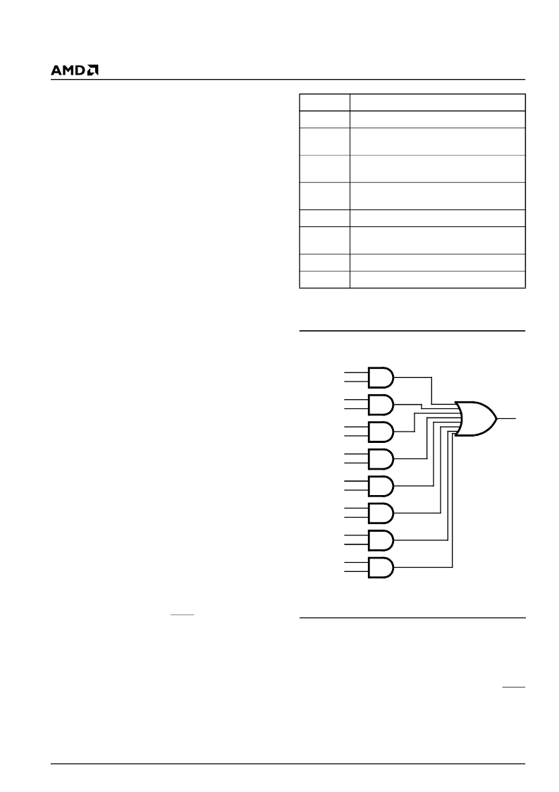
Each status signal is ANDed with its corresponding
enable signal. The enabled status signals run to a com-
mon OR gate:
The output from the OR gate is run through a pulse
stretcher, which consists of a 3-bit shift register clocked
at 38 Hz. The data input of the shift register is at logic
0. The OR gate output asynchronously sets all three
bits of the shift register when its output goes active. The
output of the shift register controls the associated LEDx
pin. Thus, the pulse stretcher provides an LED output
of 52 ms to 78 ms.
Signal
Behavior
COL
Active during collision activity on the network
FDLS
Active when Full Duplex operation is enabled
and functioning on the selected network port
JAB
Active when the PCnet-ISA II is jabbering on
the network
LNKST
Active during Link OK Not active during Link
Down
RCV
Active while receiving data
RVPOL
Active during receive polarity is OK Not active
during reverse receive polarity
RCVADDM
Active during Receive with Address Match
XMT
Active while transmitting data
AND
FDLS
FDLSE
AND
RCVM
RCVM E
AND
XMT
XMT E
AND
RVPOL
RVPOL E
AND
RCV
RCV E
AND
JAB
JAB E
AND
COL
COL E
OR
To
Pulse
Stretcher
AND
RCVADDM
RCVADDE
19364B-22
LED Control Logic
相關(guān)PDF資料 |
PDF描述 |
|---|---|
| AM79C961AVIW | PCnet⑩-ISA II Jumperless, Full Duplex Single-Chip Ethernet Controller for ISA |
| Am79C965A | PCnet?-32 Single-Chip 32-Bit Ethernet Controller |
| AM79C970AKCW | PCnet-PCI II Single-Chip Full-Duplex Ethernet Controller for PCI Local Bus Product |
| AM79C970AKC | PCnet-PCI II Single-Chip Full-Duplex Ethernet Controller for PCI Local Bus Product |
| AM79C970A | PCnet-PCI II Single-Chip Full-Duplex Ethernet Controller for PCI Local Bus Product |
相關(guān)代理商/技術(shù)參數(shù) |
參數(shù)描述 |
|---|---|
| AM79C961AVI | 制造商:Rochester Electronics LLC 功能描述: |
| AM79C961AVI/W | 制造商:未知廠家 制造商全稱:未知廠家 功能描述:LAN Node Controller |
| AM79C961AVI\\W | 制造商:Rochester Electronics LLC 功能描述: |
| AM79C961AVI\W | 制造商:Rochester Electronics LLC 功能描述: |
| AM79C961AVIW | 制造商:AMD 制造商全稱:Advanced Micro Devices 功能描述:PCnet⑩-ISA II Jumperless, Full Duplex Single-Chip Ethernet Controller for ISA |
發(fā)布緊急采購(gòu),3分鐘左右您將得到回復(fù)。