- 您現(xiàn)在的位置:買賣IC網(wǎng) > PDF目錄378045 > PCI4410A (Texas Instruments, Inc.) PC CARD AND OHCI CONTROLLER PDF資料下載
參數(shù)資料
| 型號(hào): | PCI4410A |
| 廠商: | Texas Instruments, Inc. |
| 英文描述: | PC CARD AND OHCI CONTROLLER |
| 中文描述: | PC卡和OHCI控制器 |
| 文件頁(yè)數(shù): | 124/198頁(yè) |
| 文件大小: | 892K |
| 代理商: | PCI4410A |
第1頁(yè)第2頁(yè)第3頁(yè)第4頁(yè)第5頁(yè)第6頁(yè)第7頁(yè)第8頁(yè)第9頁(yè)第10頁(yè)第11頁(yè)第12頁(yè)第13頁(yè)第14頁(yè)第15頁(yè)第16頁(yè)第17頁(yè)第18頁(yè)第19頁(yè)第20頁(yè)第21頁(yè)第22頁(yè)第23頁(yè)第24頁(yè)第25頁(yè)第26頁(yè)第27頁(yè)第28頁(yè)第29頁(yè)第30頁(yè)第31頁(yè)第32頁(yè)第33頁(yè)第34頁(yè)第35頁(yè)第36頁(yè)第37頁(yè)第38頁(yè)第39頁(yè)第40頁(yè)第41頁(yè)第42頁(yè)第43頁(yè)第44頁(yè)第45頁(yè)第46頁(yè)第47頁(yè)第48頁(yè)第49頁(yè)第50頁(yè)第51頁(yè)第52頁(yè)第53頁(yè)第54頁(yè)第55頁(yè)第56頁(yè)第57頁(yè)第58頁(yè)第59頁(yè)第60頁(yè)第61頁(yè)第62頁(yè)第63頁(yè)第64頁(yè)第65頁(yè)第66頁(yè)第67頁(yè)第68頁(yè)第69頁(yè)第70頁(yè)第71頁(yè)第72頁(yè)第73頁(yè)第74頁(yè)第75頁(yè)第76頁(yè)第77頁(yè)第78頁(yè)第79頁(yè)第80頁(yè)第81頁(yè)第82頁(yè)第83頁(yè)第84頁(yè)第85頁(yè)第86頁(yè)第87頁(yè)第88頁(yè)第89頁(yè)第90頁(yè)第91頁(yè)第92頁(yè)第93頁(yè)第94頁(yè)第95頁(yè)第96頁(yè)第97頁(yè)第98頁(yè)第99頁(yè)第100頁(yè)第101頁(yè)第102頁(yè)第103頁(yè)第104頁(yè)第105頁(yè)第106頁(yè)第107頁(yè)第108頁(yè)第109頁(yè)第110頁(yè)第111頁(yè)第112頁(yè)第113頁(yè)第114頁(yè)第115頁(yè)第116頁(yè)第117頁(yè)第118頁(yè)第119頁(yè)第120頁(yè)第121頁(yè)第122頁(yè)第123頁(yè)當(dāng)前第124頁(yè)第125頁(yè)第126頁(yè)第127頁(yè)第128頁(yè)第129頁(yè)第130頁(yè)第131頁(yè)第132頁(yè)第133頁(yè)第134頁(yè)第135頁(yè)第136頁(yè)第137頁(yè)第138頁(yè)第139頁(yè)第140頁(yè)第141頁(yè)第142頁(yè)第143頁(yè)第144頁(yè)第145頁(yè)第146頁(yè)第147頁(yè)第148頁(yè)第149頁(yè)第150頁(yè)第151頁(yè)第152頁(yè)第153頁(yè)第154頁(yè)第155頁(yè)第156頁(yè)第157頁(yè)第158頁(yè)第159頁(yè)第160頁(yè)第161頁(yè)第162頁(yè)第163頁(yè)第164頁(yè)第165頁(yè)第166頁(yè)第167頁(yè)第168頁(yè)第169頁(yè)第170頁(yè)第171頁(yè)第172頁(yè)第173頁(yè)第174頁(yè)第175頁(yè)第176頁(yè)第177頁(yè)第178頁(yè)第179頁(yè)第180頁(yè)第181頁(yè)第182頁(yè)第183頁(yè)第184頁(yè)第185頁(yè)第186頁(yè)第187頁(yè)第188頁(yè)第189頁(yè)第190頁(yè)第191頁(yè)第192頁(yè)第193頁(yè)第194頁(yè)第195頁(yè)第196頁(yè)第197頁(yè)第198頁(yè)
6
–
4
6.3
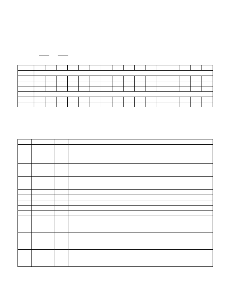
Socket Present State Register
The socket present state register reports information about the socket interface. Write transactions to the socket force
event register (CardBus offset 0Ch, see Section 6.4) are reflected here, as well as general socket-interface status.
Information about PC Card V
CC
support and card type is updated only at each insertion. Also, note that the PCI4410A
device uses CCD1 and CCD2 during card identification, and changes on these signals during this operation are not
reflected in this register. See Table 6
–
4 for a complete description of the register contents.
Bit
31
30
29
28
27
26
25
24
23
22
21
20
19
18
17
16
Name
Socket present state
Type
R
R
R
R
R
R
R
R
R
R
R
R
R
R
R
R
Default
0
0
1
1
0
0
0
0
0
0
0
0
0
0
0
0
Bit
15
14
13
12
11
10
9
8
7
6
5
4
3
2
1
0
Name
Socket present state
Type
R
R
R
R
R
R
R
R
R
R
R
R
R
R
R
R
Default
0
0
0
0
0
0
0
0
0
X
0
0
0
X
X
X
Register:
Type:
Offset:
Default:
Socket present state
Read-only
CardBus socket address + 08h
3000 00XXh
Table 6
–
4. Socket Present State Register Description
BIT
SIGNAL
TYPE
FUNCTION
31
YVSOCKET
R
YV socket. Bit 31 indicates whether or not the socket can supply VCC = Y.Y V to PC Cards. The PCI4410A
device does not support Y.Y-V VCC; therefore, this bit is hardwired to 0.
XV socket. Bit 30 indicates whether or not the socket can supply VCC = X.X V to PC Cards. The PCI4410A
device does not support X.X-V VCC; therefore, this bit is hardwired to 0.
3-V socket. Bit 29 indicates whether or not the socket can supply VCC = 3.3 V to PC Cards. The PCI4410A
device does support 3.3-V VCC; therefore, this bit always is set unless overridden by the socket force event
register (CardBus offset 0Ch, see Section 6.4).
30
XVSOCKET
R
29
3VSOCKET
R
28
5VSOCKET
R
5-V socket. Bit 28 indicates whether or not the socket can supply VCC = 5 V to PC Cards. The PCI4410A
device does support 5-V VCC; therefore, this bit always is set unless overridden by the socket force event
register (CardBus offset 0Ch, see Section 6.4).
27
–
14
RSVD
R
Reserved. Bits 27
–
14 return 0s when read.
13
YVCARD
R
YV card. Bit 13 indicates whether or not the PC Card inserted in the socket supports VCC = Y.Y V.
XV card. Bit 12 indicates whether or not the PC Card inserted in the socket supports VCC = X.X V.
3-V card. Bit 11 indicates whether or not the PC Card inserted in the socket supports VCC = 3.3 V.
5-V card. Bit 10 indicates whether or not the PC Card inserted in the socket supports VCC = 5 V.
Bad VCC request. Bit 9 indicates that the host software has requested that the socket be powered at an
invalid voltage.
0 = Normal operation (default)
1 = Invalid VCC request by host software
Data lost. Bit 8 indicates that a PC Card removal event may have caused lost data because the cycle did
not terminate properly or because write data still resides in the PCI4410A device.
0 = Normal operation (default)
1 = Potential data loss due to card removal
12
XVCARD
R
11
3VCARD
R
10
5VCARD
R
9
BADVCCREQ
R
8
DATALOST
R
7
NOTACARD
R
Not a card. Bit 7 indicates that an unrecognizable PC Card is inserted in the socket. This bit is not updated
until a valid PC Card is inserted into the socket.
0 = Normal operation (default)
1 = Unrecognizable PC Card detected
相關(guān)PDF資料 |
PDF描述 |
|---|---|
| PCI4510PDV | PC CARD AND INTEGRATED 1394A-2000 OHCI TWO PORT PHY/LINK LAYER CONTROLLER |
| PCI4515 | SINGLE SOCKET CARDBUS CONTROLLER WITH INTEGRATED |
| PCI4515GHK | SINGLE SOCKET CARDBUS CONTROLLER WITH INTEGRATED |
| PCI4515ZHK | SINGLE SOCKET CARDBUS CONTROLLER WITH INTEGRATED |
| PCI6420 | Integrated 2-Slot PC Card & Dedicated Flash Media Controller |
相關(guān)代理商/技術(shù)參數(shù) |
參數(shù)描述 |
|---|---|
| PCI4410AGHK | 功能描述:外圍驅(qū)動(dòng)器與原件 - PCI INTEGRATED PC CARD RoHS:否 制造商:PLX Technology 工作電源電壓: 最大工作溫度: 安裝風(fēng)格:SMD/SMT 封裝 / 箱體:FCBGA-1156 封裝:Tray |
| PCI4410APDV | 功能描述:外圍驅(qū)動(dòng)器與原件 - PCI INTEGRATED PC CARD RoHS:否 制造商:PLX Technology 工作電源電壓: 最大工作溫度: 安裝風(fēng)格:SMD/SMT 封裝 / 箱體:FCBGA-1156 封裝:Tray |
| PCI4410GHK | 制造商:Rochester Electronics LLC 功能描述:- Bulk 制造商:Texas Instruments 功能描述: |
| PCI4410PDV | 制造商:Rochester Electronics LLC 功能描述:- Bulk |
| PCI4450 | 制造商:TI 制造商全稱:Texas Instruments 功能描述:PC Card and OHCI Controller |
發(fā)布緊急采購(gòu),3分鐘左右您將得到回復(fù)。