- 您現(xiàn)在的位置:買賣IC網(wǎng) > PDF目錄378056 > PM7383-PI (PMC-Sierra, Inc.) FRAME ENGINE AND DATA LINK MANAGER 32A256 PDF資料下載
參數(shù)資料
| 型號(hào): | PM7383-PI |
| 廠商: | PMC-Sierra, Inc. |
| 英文描述: | FRAME ENGINE AND DATA LINK MANAGER 32A256 |
| 中文描述: | 框架引擎和數(shù)據(jù)鏈路管理32A256 |
| 文件頁數(shù): | 133/231頁 |
| 文件大小: | 1947K |
| 代理商: | PM7383-PI |
第1頁第2頁第3頁第4頁第5頁第6頁第7頁第8頁第9頁第10頁第11頁第12頁第13頁第14頁第15頁第16頁第17頁第18頁第19頁第20頁第21頁第22頁第23頁第24頁第25頁第26頁第27頁第28頁第29頁第30頁第31頁第32頁第33頁第34頁第35頁第36頁第37頁第38頁第39頁第40頁第41頁第42頁第43頁第44頁第45頁第46頁第47頁第48頁第49頁第50頁第51頁第52頁第53頁第54頁第55頁第56頁第57頁第58頁第59頁第60頁第61頁第62頁第63頁第64頁第65頁第66頁第67頁第68頁第69頁第70頁第71頁第72頁第73頁第74頁第75頁第76頁第77頁第78頁第79頁第80頁第81頁第82頁第83頁第84頁第85頁第86頁第87頁第88頁第89頁第90頁第91頁第92頁第93頁第94頁第95頁第96頁第97頁第98頁第99頁第100頁第101頁第102頁第103頁第104頁第105頁第106頁第107頁第108頁第109頁第110頁第111頁第112頁第113頁第114頁第115頁第116頁第117頁第118頁第119頁第120頁第121頁第122頁第123頁第124頁第125頁第126頁第127頁第128頁第129頁第130頁第131頁第132頁當(dāng)前第133頁第134頁第135頁第136頁第137頁第138頁第139頁第140頁第141頁第142頁第143頁第144頁第145頁第146頁第147頁第148頁第149頁第150頁第151頁第152頁第153頁第154頁第155頁第156頁第157頁第158頁第159頁第160頁第161頁第162頁第163頁第164頁第165頁第166頁第167頁第168頁第169頁第170頁第171頁第172頁第173頁第174頁第175頁第176頁第177頁第178頁第179頁第180頁第181頁第182頁第183頁第184頁第185頁第186頁第187頁第188頁第189頁第190頁第191頁第192頁第193頁第194頁第195頁第196頁第197頁第198頁第199頁第200頁第201頁第202頁第203頁第204頁第205頁第206頁第207頁第208頁第209頁第210頁第211頁第212頁第213頁第214頁第215頁第216頁第217頁第218頁第219頁第220頁第221頁第222頁第223頁第224頁第225頁第226頁第227頁第228頁第229頁第230頁第231頁
RELEASED
DATASHEET
PM7383 FREEDM-32A256
ISSUE 1
PMC-2010336
FRAME ENGINE AND DATA LINK MANAGER 32A256
PROPRIETARY AND CONFIDENTIAL
125
16-byte blocks. XFER[3:0] reflects the value written until the completion of a
subsequent indirect channel read operation.
To prevent lockup, the channel transfer size (XFER[3:0]) can be configured to
be less than or equal to the start transmission level set by LEVEL[3:0] and
TRANS. Alternatively, the channel transfer size can be set such that the total
number of blocks in the logical channel FIFO minus the start transmission
level is an integer multiple of the channel transfer size.
FLAG[2:0]:
The flag insertion control (FLAG[2:0]) configures the minimum number of
flags or bytes of idle bits the HDLC processor inserts between HDLC packets.
The value of FLAG[2:0] to be written to the channel provision RAM, in an
indirect channel write operation, must be set up in this register before
triggering the write. The minimum number of flags or bytes of idle (8 bits of
1’s) inserted between HDLC packets is shown in the table below. FLAG[2:0]
reflects the value written until the completion of a subsequent indirect channel
read operation.
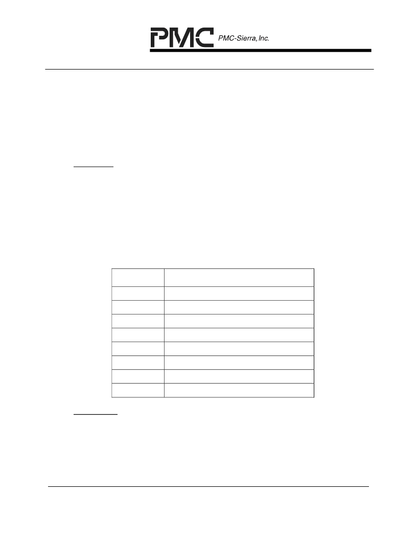
Table 13 – FLAG[2:0] Settings
FLAG[2:0]
Minimum Number of Flag/Idle Bytes
000
1 flag / 0 Idle byte
001
2 flags / 0 idle byte
010
4 flags / 2 idle bytes
011
8 flags / 6 idle bytes
100
16 flags / 14 idle bytes
101
32 flags / 30 idle bytes
110
64 flags / 62 idle bytes
111
128 flags / 126 idle bytes
LEVEL[3:0]:
The indirect channel FIFO trigger level (LEVEL[3:0]), in concert with the
TRANS bit, configure the various channel FIFO free space levels which
trigger the HDLC processor to start transmission of a HDLC packet as well as
trigger the partial packet buffer to request data from the TAPI256 as shown in
the following table. The channel FIFO trigger level to be written to the
channel provision RAM, in an indirect write operation, must be set up in this
相關(guān)PDF資料 |
PDF描述 |
|---|---|
| PM7384 | Frame Engine and Data Link Manager |
| PM7384-BI | FRAME ENGINE AND DATA LINK MANAGER 84P672 |
| PM7385 | Frame Engine and Data Link Manager |
| PM7385-BI | 84 LINK, 672 CHANNEL FRAME ENGINE AND DATA LINK MANAGER WITH ANY-PHY PACKET INTERFACE |
| PM7388 | Frame Engine and Datalink Manager |
相關(guān)代理商/技術(shù)參數(shù) |
參數(shù)描述 |
|---|---|
| PM7384 | 制造商:PMC 制造商全稱:PMC 功能描述:Frame Engine and Data Link Manager |
| PM7384-BI | 制造商:PMC 制造商全稱:PMC 功能描述:FRAME ENGINE AND DATA LINK MANAGER 84P672 |
| PM7385 | 制造商:PMC 制造商全稱:PMC 功能描述:Frame Engine and Data Link Manager |
發(fā)布緊急采購,3分鐘左右您將得到回復(fù)。