- 您現(xiàn)在的位置:買賣IC網(wǎng) > PDF目錄378056 > PM7383-PI (PMC-Sierra, Inc.) FRAME ENGINE AND DATA LINK MANAGER 32A256 PDF資料下載
參數(shù)資料
| 型號: | PM7383-PI |
| 廠商: | PMC-Sierra, Inc. |
| 英文描述: | FRAME ENGINE AND DATA LINK MANAGER 32A256 |
| 中文描述: | 框架引擎和數(shù)據(jù)鏈路管理32A256 |
| 文件頁數(shù): | 206/231頁 |
| 文件大小: | 1947K |
| 代理商: | PM7383-PI |
第1頁第2頁第3頁第4頁第5頁第6頁第7頁第8頁第9頁第10頁第11頁第12頁第13頁第14頁第15頁第16頁第17頁第18頁第19頁第20頁第21頁第22頁第23頁第24頁第25頁第26頁第27頁第28頁第29頁第30頁第31頁第32頁第33頁第34頁第35頁第36頁第37頁第38頁第39頁第40頁第41頁第42頁第43頁第44頁第45頁第46頁第47頁第48頁第49頁第50頁第51頁第52頁第53頁第54頁第55頁第56頁第57頁第58頁第59頁第60頁第61頁第62頁第63頁第64頁第65頁第66頁第67頁第68頁第69頁第70頁第71頁第72頁第73頁第74頁第75頁第76頁第77頁第78頁第79頁第80頁第81頁第82頁第83頁第84頁第85頁第86頁第87頁第88頁第89頁第90頁第91頁第92頁第93頁第94頁第95頁第96頁第97頁第98頁第99頁第100頁第101頁第102頁第103頁第104頁第105頁第106頁第107頁第108頁第109頁第110頁第111頁第112頁第113頁第114頁第115頁第116頁第117頁第118頁第119頁第120頁第121頁第122頁第123頁第124頁第125頁第126頁第127頁第128頁第129頁第130頁第131頁第132頁第133頁第134頁第135頁第136頁第137頁第138頁第139頁第140頁第141頁第142頁第143頁第144頁第145頁第146頁第147頁第148頁第149頁第150頁第151頁第152頁第153頁第154頁第155頁第156頁第157頁第158頁第159頁第160頁第161頁第162頁第163頁第164頁第165頁第166頁第167頁第168頁第169頁第170頁第171頁第172頁第173頁第174頁第175頁第176頁第177頁第178頁第179頁第180頁第181頁第182頁第183頁第184頁第185頁第186頁第187頁第188頁第189頁第190頁第191頁第192頁第193頁第194頁第195頁第196頁第197頁第198頁第199頁第200頁第201頁第202頁第203頁第204頁第205頁當(dāng)前第206頁第207頁第208頁第209頁第210頁第211頁第212頁第213頁第214頁第215頁第216頁第217頁第218頁第219頁第220頁第221頁第222頁第223頁第224頁第225頁第226頁第227頁第228頁第229頁第230頁第231頁
RELEASED
DATASHEET
PM7383 FREEDM-32A256
ISSUE 1
PMC-2010336
FRAME ENGINE AND DATA LINK MANAGER 32A256
PROPRIETARY AND CONFIDENTIAL
198
The start of all burst data transfers is qualified with the TSX signal and an in-band
channel address on TXDATA[15:0] to associate the data to follow with a HDLC
channel. The TEOP signal indicates the end of valid packet data. The TMOD
and TERR signals held low except at the end of a packet (TEOP set high).
The FREEDM-32A256 starts driving the TRDY signal one TXCLK cycle after TSX
is sampled high. Upon sampling the TRDY signal high, the external controller
completes the current burst data transfer. The FREEDM-32A256 tristates the
TRDY signal one TXCLK cycle after it has been driven high. This is the case for
the first burst data transfer in Figure 26. In the second burst data transfer, the
FREEDM-32A256 drives the TRDY signal low to indicate that the FIFOs in the
TAPI256 are full and no further data may be transferred. Upon sampling the
TRDY signal low, the external controller must hold the last valid word of data on
TXDATA[15:0]. The FREEDM-32A256 may drive TRDY low for an indeterminate
number of TXCLK cycles. During this time, the external controller must wait and
is not permitted to begin another burst data transfer until TRDY is sampled high.
When the TAPI256 has at least one empty FIFO, the FREEDM-32A256 drives
the TRDY signal high. Upon sampling the TRDY signal high, the external
controller completes the current burst data transfer. The FREEDM-32A256
tristates the TRDY signal one TXCLK cycle after it has been driven high.
The external controller must sample the TRDY signal high before it can begin the
next burst data transfer. This prevents the external controller from bombarding
the FREEDM-32A256 device with small packets and allows the FREEDM-
32A256 to perform the necessary house-keeping and clean-up associated with
the ending of burst data transfers. This protocol also ensures that transitions
between burst data transfers do not require any extra per channel storage,
thereby simplifying implementation of both the external controller and the
FREEDM-32A256 device. Figure 27 illustrates this condition.
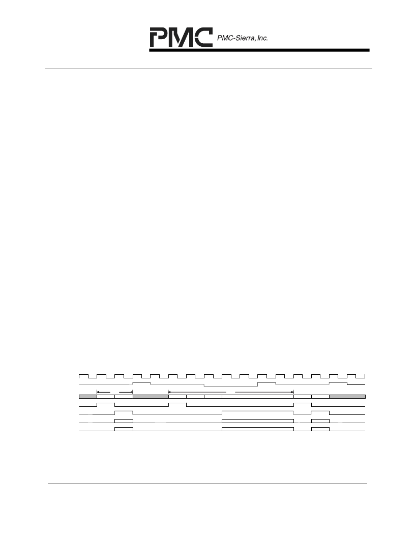
Figure 27 – Transmit APPI Timing (Special Conditions)
CH 0
D0
CH 255
D0
D1
D2
CH 2
D0
Dev 5
Dev 3
TXCLK
TRDY
TXDATA[15:0]
TSX
TEOP
TMOD
TERR
Figure 27 shows two special conditions – (1) the transfer of a one word packet
illustrating how the external controller must wait until TRDY has been sampled
相關(guān)PDF資料 |
PDF描述 |
|---|---|
| PM7384 | Frame Engine and Data Link Manager |
| PM7384-BI | FRAME ENGINE AND DATA LINK MANAGER 84P672 |
| PM7385 | Frame Engine and Data Link Manager |
| PM7385-BI | 84 LINK, 672 CHANNEL FRAME ENGINE AND DATA LINK MANAGER WITH ANY-PHY PACKET INTERFACE |
| PM7388 | Frame Engine and Datalink Manager |
相關(guān)代理商/技術(shù)參數(shù) |
參數(shù)描述 |
|---|---|
| PM7384 | 制造商:PMC 制造商全稱:PMC 功能描述:Frame Engine and Data Link Manager |
| PM7384-BI | 制造商:PMC 制造商全稱:PMC 功能描述:FRAME ENGINE AND DATA LINK MANAGER 84P672 |
| PM7385 | 制造商:PMC 制造商全稱:PMC 功能描述:Frame Engine and Data Link Manager |
發(fā)布緊急采購,3分鐘左右您將得到回復(fù)。