- 您現(xiàn)在的位置:買賣IC網(wǎng) > PDF目錄373785 > ZL50018GAC (ZARLINK SEMICONDUCTOR INC) 2 K Digital Switch with Enhanced Stratum 3 DPLL PDF資料下載
參數(shù)資料
| 型號: | ZL50018GAC |
| 廠商: | ZARLINK SEMICONDUCTOR INC |
| 元件分類: | 路由/交換 |
| 英文描述: | 2 K Digital Switch with Enhanced Stratum 3 DPLL |
| 中文描述: | TELECOM, DIGITAL TIME SWITCH, PBGA256 |
| 封裝: | 17 X 17 MM, 1.61 MM HEIGHT, PLASTIC, MS-034, BGA-256 |
| 文件頁數(shù): | 45/136頁 |
| 文件大?。?/td> | 1448K |
| 代理商: | ZL50018GAC |
第1頁第2頁第3頁第4頁第5頁第6頁第7頁第8頁第9頁第10頁第11頁第12頁第13頁第14頁第15頁第16頁第17頁第18頁第19頁第20頁第21頁第22頁第23頁第24頁第25頁第26頁第27頁第28頁第29頁第30頁第31頁第32頁第33頁第34頁第35頁第36頁第37頁第38頁第39頁第40頁第41頁第42頁第43頁第44頁當(dāng)前第45頁第46頁第47頁第48頁第49頁第50頁第51頁第52頁第53頁第54頁第55頁第56頁第57頁第58頁第59頁第60頁第61頁第62頁第63頁第64頁第65頁第66頁第67頁第68頁第69頁第70頁第71頁第72頁第73頁第74頁第75頁第76頁第77頁第78頁第79頁第80頁第81頁第82頁第83頁第84頁第85頁第86頁第87頁第88頁第89頁第90頁第91頁第92頁第93頁第94頁第95頁第96頁第97頁第98頁第99頁第100頁第101頁第102頁第103頁第104頁第105頁第106頁第107頁第108頁第109頁第110頁第111頁第112頁第113頁第114頁第115頁第116頁第117頁第118頁第119頁第120頁第121頁第122頁第123頁第124頁第125頁第126頁第127頁第128頁第129頁第130頁第131頁第132頁第133頁第134頁第135頁第136頁
ZL50018
Data Sheet
45
Zarlink Semiconductor Inc.
1.326 ms (61 ppm). The width of the register and the limiter circuitry, if not bypassed, provide a maximum phase
change alignment speed of 186 ppm.
The limiter circuitry can be bypassed by programming BLM (bit 13) in the Bandwidth Control Register (BWCR).
Bypassing limiter (combined with choice of other parameters in the BWCR register) can achieve very fast lock of
the output clock to the selected input reference. A side effect of the bypassing limiter is manifested through much
higher intrinsic jitter. Once the bypassing is stopped, the jitter characteristics are guaranteed. The phase alignment
speed default value is 56 ppm.
15.4 Fast Locking Mode
If very fast locking feature (i.e., locking time in order of 1 s) is desirable, the Bandwidth Control Register (BWCR)
can be programmed to accommodate the feature for any selected corner frequency. In this mode, the DPLL’s phase
alignment speed limiter is bypassed. See Table 39, “Bandwidth Control Register (BWCR) Bits” on page 73.
Semi-fast locking mode does not bypass the internal phase alignment speed limiter, thereby maintaining phase
alignment speed. This mode can be achieved by programming the SM_FST bit in the DPLL Control Register.
In freerun mode, the DPLL does not lock to any reference. It is important that the device is not simultaneously in
freerun mode (see the RCCR Register) and fast lock mode (see the BWCR Register). Otherwise, the output frame
pulse may not be generated correctly.
15.5 Reference Monitoring
The quality of the four input reference clocks is continuously monitored by the reference monitors. There are
separate reference monitor circuits for the four DPLL references. References are checked for short phase (single
period) deviations as well as for frequency (multi-period) deviations with hysteresis.
The Reference Status Register (RSR) reports the status of the reference monitors. The register bits are described
in Table 57 on page 88. The Reference Mask Register (RMR) allows users to ignore the monitoring features of the
reference monitors. See Table 58 on page 89 for details.
15.6 Single Period Reference Monitoring
Values for short phase deviations (upper and lower limit) are programmable through registers. The unit of the binary
values of these numbers is 100 MHz clock period (10 ns). Single period deviation limits are more relaxed than multi
period limits, and are used for early detection of the reference loss, or huge phase jumps.
Registers containing the lower and upper limits of the acceptance range for the single input reference period
measurement are: Reference Lower Limit Registers: R0LLR, R1LLR, R2LLR and R3LLR and the Reference Upper
Limit Registers: R0ULR, R1ULR, R2ULR and R3ULR.
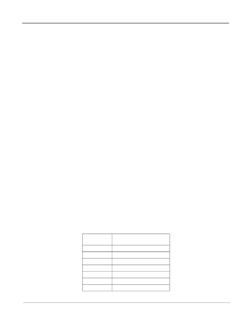
The default values for the upper and lower limits are shown in the following table:
Reference
Frequency
8 kHz
1.544 MHz
2.048 MHz
4.096 MHz
8.192 MHz
16.384 MHz
19.44 MHz
Comment
10 UI p-p
0.3 UI p-p
0.2 UI p-p
0.2 UI p-p
0.2 UI p-p
0.2 UI p-p
0.2 UI p-p
Table 11 - Values for Single Period Limits
相關(guān)PDF資料 |
PDF描述 |
|---|---|
| ZL50018QCC | 2 K Digital Switch with Enhanced Stratum 3 DPLL |
| ZL50019 | Enhanced 2 K Digital Switch with Stratum 4E DPLL |
| ZL50019GAC | Enhanced 2 K Digital Switch with Stratum 4E DPLL |
| ZL50019QCC | Enhanced 2 K Digital Switch with Stratum 4E DPLL |
| ZL50022 | Enhanced 4 K Digital Switch with Stratum 4E DPLL |
相關(guān)代理商/技術(shù)參數(shù) |
參數(shù)描述 |
|---|---|
| ZL50018GAG2 | 制造商:Microsemi Corporation 功能描述:SWIT FABRIC 2K X 2K 1.8V/3.3V 256BGA - Trays 制造商:MICROSEMI CONSUMER MEDICAL PRODUCT GROUP 功能描述:IC TDM SWITCH 2K-CH ENH 256PBGA 制造商:Microsemi Corporation 功能描述:IC TDM SWITCH 2K-CH ENH 256PBGA |
| ZL50018QCC | 制造商:Microsemi Corporation 功能描述:SWIT FABRIC 2K X 2K 1.8V/3.3V 256LQFP - Trays |
| ZL50018QCG1 | 制造商:Microsemi Corporation 功能描述:PB FREE 2K+ RATE CONVERSION AND S3 DPLL - Trays 制造商:MICROSEMI CONSUMER MEDICAL PRODUCT GROUP 功能描述:IC TDM SWITCH 2K-CH ENH 256LQFP |
| ZL50019 | 制造商:ZARLINK 制造商全稱:Zarlink Semiconductor Inc 功能描述:Enhanced 2 K Digital Switch with Stratum 4E DPLL |
| ZL50019_06 | 制造商:ZARLINK 制造商全稱:Zarlink Semiconductor Inc 功能描述:Enhanced 2 K Digital Switch with Stratum 4E DPLL |
發(fā)布緊急采購,3分鐘左右您將得到回復(fù)。