- 您現(xiàn)在的位置:買賣IC網(wǎng) > PDF目錄366329 > ACE9050 (Mitel Networks Corporation) System Controller and Data Modem(為蜂窩式手機(jī)提供控制和邏輯接口功能的系統(tǒng)控制器和數(shù)據(jù)調(diào)制解調(diào)器) PDF資料下載
參數(shù)資料
| 型號: | ACE9050 |
| 廠商: | Mitel Networks Corporation |
| 英文描述: | System Controller and Data Modem(為蜂窩式手機(jī)提供控制和邏輯接口功能的系統(tǒng)控制器和數(shù)據(jù)調(diào)制解調(diào)器) |
| 中文描述: | 系統(tǒng)控制器和數(shù)據(jù)調(diào)制解調(diào)器(為蜂窩式手機(jī)提供控制和邏輯接口功能的系統(tǒng)控制器和數(shù)據(jù)調(diào)制解調(diào)器) |
| 文件頁數(shù): | 43/52頁 |
| 文件大小: | 366K |
| 代理商: | ACE9050 |
第1頁第2頁第3頁第4頁第5頁第6頁第7頁第8頁第9頁第10頁第11頁第12頁第13頁第14頁第15頁第16頁第17頁第18頁第19頁第20頁第21頁第22頁第23頁第24頁第25頁第26頁第27頁第28頁第29頁第30頁第31頁第32頁第33頁第34頁第35頁第36頁第37頁第38頁第39頁第40頁第41頁第42頁當(dāng)前第43頁第44頁第45頁第46頁第47頁第48頁第49頁第50頁第51頁第52頁

ACE9050
43
PORT5
Read/Write (Note 1)
Bits
5:4
0
OUT2.2_SEL
PWM1MUX
00 = OUT_PORT2[2] (Note 2)
01 = PWM2
10 = Latch 2
11 = Not valid
0 = PWM1
1 = OUT_PORT2[1] (note 2)
Name
Description
NOTES
1. These register bits are also described in the External Ports and
Multiplexer section.
2. Reset state.
Table 95
6. BEEP ALARM RING (BAR) TONE GENERATOR
The ACE9050 provides a Beep Alarm and Ring Tone generator
unit. This provides a digital output pulse train. The high and low
time can be programmed with software. It is thus possible to vary
the output tone frequency, period and volume. The pulse train
can also be disabled whereupon the output will be set low. Within
the system this output can be used to control a buzzer driver.
External Pin
BAR
Output (Pin 96)
CMOS output which is determined by the state of the registers
in the BAR block (BARHIGH, BARLOW and BARENABLE).
Associated Registers
Write
Register
BARHIGH
BARLOW
BARENABLE
BAR ON time
BAR OFF time
0 = BAR output low
1 = BAR output pulsing
Description
Bits
7:0
7:0
0
Table 96
Programming
The two programmable 8-bit registers determine the ON and
OFF times in steps of approximately 8
μ
s (7·9
μ
s). The maximum
ON and OFF times are approximately 2ms each (2·02ms). The
following formula is used to calculate the actual times:
BAR ON Time = (256
2
BARHIGH[7:0])
3
7·93
μ
s
BAR OFF Time = (256
2
BARLOW[7:0])
3
7·93
μ
s
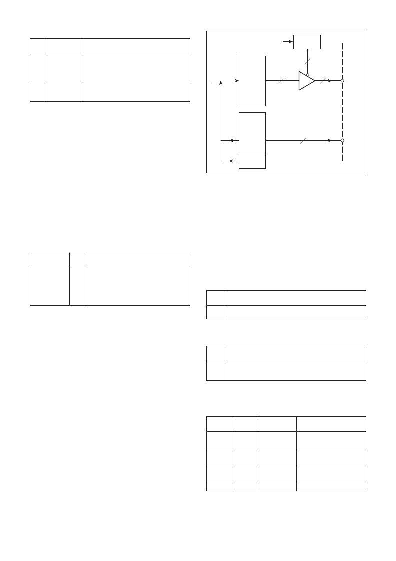
7. KEYPAD INTERFACE AND CHIP IDENTITY
The Keyboard interface consists of a 5-bit output port, a 4-bit
input port and associated registers to read, write and configure
the ports (see Fig. 25).
Alternatively these ports can be used for general I/O. The
output port drive configuration can be set via software to provide
the system designer with full flexibility. The port has tristate
output buffers, controlled by the KPOT register. By programming
KEYP and KPOT appropriately the outputs can be configured to
drive in the following ways:
High impedance
Driving logic output (high or low)
Open drain
Open source.
[3:0]
KPI INPUTS
KEYP
WRITE
KEYP
READ
5
5
[7:4]
IDENT
5
4
KPOT
DATA BUS
DATA BUS
KPO [4:0]
KPI [3:0]
59-55
66-69
010
Fig. 25 Keyport configuration
Output Port
The output port has five individual outputs, which can be used
as scanning outputs connected to a keyboard matrix, or can be
used for other general purposes .
External Pins
KP0[4: 0]
Outputs (Pins 59: 55)
The state of these outputs are defined by the respective bits in
the internal registers KEYP and KPOT.
Associated Registers
KEYP
Write
Keypad output port register
Description
Bits
4:0
Table 97
KPOT
Write
Output Port driver configuration
Description
Bits
4:0
0 = Output driven to level set by relevant KEYP bit
1 = Output tristate
Sets or clears associated bit in Output Port register
Table 98
Programming Examples
The following bit patterns thus yield the following output
configurations:
KPOT
Output
Description
Logic drive
Logic drive
Open drain
Open drain
Open source
Open source
High impedance
0
0
0
1
0
1
1
0
1
0
Z
1
Z
Z
0
1
0
0
1
1
X
Table 99
KEYP
Write
相關(guān)PDF資料 |
PDF描述 |
|---|---|
| ACE9050 | System Controller and Data Modem Advance Information |
| ACFA-450 | AM CERAMIC FILTERS |
| ACFA-455 | AM CERAMIC FILTERS |
| ACFA-459 | AM CERAMIC FILTERS |
| ACFA-468 | AM CERAMIC FILTERS |
相關(guān)代理商/技術(shù)參數(shù) |
參數(shù)描述 |
|---|---|
| ACE9050C/IW/FP1N | 制造商:Microsemi Corporation 功能描述:PB FREE SYSTEM CONTROLLER & DATA MODEM - Bulk |
| ACE9050C/IW/FP1Q | 制造商:Microsemi Corporation 功能描述:PB FREE SYSTEM CONTROLLER & DATA MODEM - Bulk |
| ace9050c/iw/fp8q | 制造商:Rochester Electronics LLC 功能描述: 制造商:Zarlink Semiconductor Inc 功能描述: |
| ace9050d/ig/gp1n | 制造商:Microsemi Corporation 功能描述:CNTRLR AND DATA MODEM 100LQFP - Bulk 制造商:Rochester Electronics LLC 功能描述: 制造商:Zarlink Semiconductor Inc 功能描述: |
| ACE9050D/IG/GP2N | 制造商:Microsemi Corporation 功能描述:CNTRLR AND DATA MODEM 100LQFP - Bulk |
發(fā)布緊急采購,3分鐘左右您將得到回復(fù)。