- 您現(xiàn)在的位置:買(mǎi)賣(mài)IC網(wǎng) > PDF目錄373891 > AD6636 (Analog Devices, Inc.) 150 MSPS Wideband Digital Down-Converter (DDC) PDF資料下載
參數(shù)資料
| 型號(hào): | AD6636 |
| 廠商: | Analog Devices, Inc. |
| 元件分類(lèi): | 數(shù)字上/下變頻 |
| 英文描述: | 150 MSPS Wideband Digital Down-Converter (DDC) |
| 中文描述: | 150MSPS的寬帶數(shù)字下變頻器(DDC) |
| 文件頁(yè)數(shù): | 20/72頁(yè) |
| 文件大?。?/td> | 1629K |
| 代理商: | AD6636 |
第1頁(yè)第2頁(yè)第3頁(yè)第4頁(yè)第5頁(yè)第6頁(yè)第7頁(yè)第8頁(yè)第9頁(yè)第10頁(yè)第11頁(yè)第12頁(yè)第13頁(yè)第14頁(yè)第15頁(yè)第16頁(yè)第17頁(yè)第18頁(yè)第19頁(yè)當(dāng)前第20頁(yè)第21頁(yè)第22頁(yè)第23頁(yè)第24頁(yè)第25頁(yè)第26頁(yè)第27頁(yè)第28頁(yè)第29頁(yè)第30頁(yè)第31頁(yè)第32頁(yè)第33頁(yè)第34頁(yè)第35頁(yè)第36頁(yè)第37頁(yè)第38頁(yè)第39頁(yè)第40頁(yè)第41頁(yè)第42頁(yè)第43頁(yè)第44頁(yè)第45頁(yè)第46頁(yè)第47頁(yè)第48頁(yè)第49頁(yè)第50頁(yè)第51頁(yè)第52頁(yè)第53頁(yè)第54頁(yè)第55頁(yè)第56頁(yè)第57頁(yè)第58頁(yè)第59頁(yè)第60頁(yè)第61頁(yè)第62頁(yè)第63頁(yè)第64頁(yè)第65頁(yè)第66頁(yè)第67頁(yè)第68頁(yè)第69頁(yè)第70頁(yè)第71頁(yè)第72頁(yè)
AD6636
Rev. 0 | Page 20 of 72
0
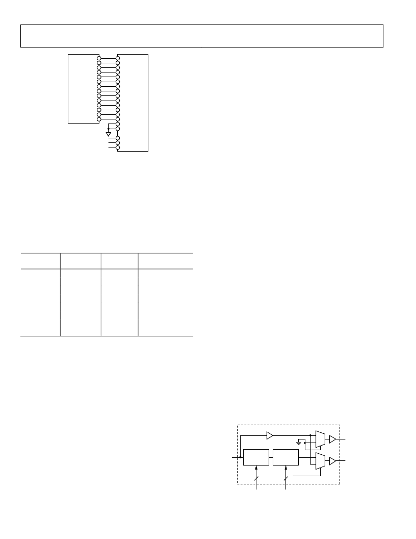
AD6645
14-BIT ADC
AD6636
D13 (MSB)
D0 (LSB)
IN15
IN2
IN1
EXP0
EXP1
IN0
EXP2
GAIN RANGING CONTROL
BITS OR GROUNDED
EXPONENT BITS
Figure 23. Typical Interconnection of the AD6645 Fixed-Point ADC
and the AD6636
Scaling with Floating-Point ADC
An example of the exponent control feature combines the
AD6600 and the AD6636. The AD6600 is an 11-bit ADC with
three bits of gain ranging. In effect, the 11-bit ADC provides the
mantissa, and the three bits of the relative signal strength
indicator (RSSI) are the exponent. Only five of the eight
available steps are used by the AD6600. See the AD6600 data
sheet for details.
Table 9. Weighting Factors for Different Exp[2:0] Values
ADC Input
Level
Exp[2:0]
Largest
000 (0)
001 (1)
010 (2)
011 (3)
100 (4)
101 (5)
110 (6)
Smallest
111 (7)
AD6636
Data
Divide-By
/1 (>> 0)
/2 (>>1)
/4 (>>2)
/8 (>>3)
/16 (>> 4)
/32 (>> 5)
/64 (>> 6)
/128(>> 7)
Signal
Attenuation (dB)
0
6
12
18
24
30
36
42
Complex (I/Q) Input Ports
The four individual ADC input ports of the AD6636 can be
configured to function as two complex input ports. Additionally,
if required, only two input ports can be made to function as a
complex port, while the remaining two input ports function as
real individual input ports.
In complex mode, Input Port A is paired with Input Port B to
receive I and Q data, respectively. Similarly, Input Port C can be
paired with Input Port D to receive I and Q data, respectively.
These two pairings are controlled individually using Bits 24 and
25 of ADC input control register.
As explained previously, each individual channel can receive
input signals from any of the four input ports using the crossbar
mux select bits in the ADC input control register. In addition to
the three bits, a 1-bit selection is provided for choosing the
complex input port option for any individual channel. For
example, if Channel 0 needs to receive complex input from
Input Ports A and B, then the mux select bits should indicate
Input Port A, and the complex input bit should be selected.
When the input ports are paired for complex input operation,
only one set of exponent bits is driven externally with gain
control output. So when Input Ports A and B form a complex
input, then EXPA[2:0] are output and, similarly, for Input Ports
C and D, EXPC[2:0] are output.
LVDS Input Ports
AD6636 input ports can be configured in two different modes:
CMOS or LVDS. In CMOS input mode, the four input ports can
be configured as two complex input ports. In LVDS mode, two
CMOS input ports each are combined to form one LVDS input
port.
CMOS Input Ports INA[15:0] and INB[15:0] form the positive
and negative differential nodes, LVDS_A+[15:0] and
LVDS_A[15:0], respectively. Similarly, INC[15:0] and
IND[15:0] form the positive and negative differential nodes,
LVDS_C+[15:0] and LVDS_C [15:0], respectively. CLKA and
CLKB form the differential pair, LVDS_CLKA+ and
LVDS_CLKA pins. Similarly, CLKC and CLKD form the
differential pair LVDS_CLKC+ and LVDS_CLKC pins.
By default, the AD6636 powers up in CMOS mode and can be
programmed to CMOS mode by using the CMOS mode bit (Bit
10 of the LVDS control register). Writing Logic 1 to Bit 8 of the
LVDS control register enables an autocalibrate routine that
calibrates the impedance of the LVDS pads to match the output
impedance of the LVDS signal source impedance. The LVDS
pads in the AD6636 have an internal impedance of 100 across
the differential signals; therefore, an external resistor is not
required.
PLL CLOCK MULTIPLIER
In the AD6636, the input clock rate must be the same as the
input data rate. In a typical digital down-converter architecture,
the clock rate is a limitation on the number of filter taps that
can be calculated in the programmable RAM coefficient filters
(MRCF, DRCF, and CRCF). For slower ADC clock rates (or for
any clock rate), this limitation can be overcome by using a PLL
clock multiplier to provide a higher clock rate to the RCF filters.
Using this clock multiplier, the internal signal processing clock
rate can be increased up to 200 MHz. The CLKA signal is used
as an input to the PLL clock multiplier.
0
CLKA
PLL_CLK
ADC_CLK
DIVIDE BY N
(1, 2, 4 OR 8)
PLL CLOCK
MULITPLIER
(4x TO 20x)
PLL CLOCK GENERATION
BYPASS_PLL
1 FOR BYPASS
N
M
2
5
0
1
1
0
Figure 24. PLL Clock Generation
相關(guān)PDF資料 |
PDF描述 |
|---|---|
| AD6636BBCZ1 | 150 MSPS Wideband Digital Down-Converter (DDC) |
| AD6636BC | 150 MSPS Wideband Digital Down-Converter (DDC) |
| AD6636CBCZ1 | 150 MSPS Wideband Digital Down-Converter (DDC) |
| AD6636PCB | 150 MSPS Wideband Digital Down-Converter (DDC) |
| AD664(中文) | Monolithic 12-Bit Quad DAC(單片12位四D/A轉(zhuǎn)換器) |
相關(guān)代理商/技術(shù)參數(shù) |
參數(shù)描述 |
|---|---|
| AD6636BBC | 制造商:Analog Devices 功能描述:Digital Down Converter 256-Pin CSP-BGA |
| AD6636BBCZ | 功能描述:IC DIGITAL DWNCONV 6CH 256CSPBGA RoHS:是 類(lèi)別:RF/IF 和 RFID >> RF 混頻器 系列:AD6636 產(chǎn)品培訓(xùn)模塊:Lead (SnPb) Finish for COTS Obsolescence Mitigation Program 標(biāo)準(zhǔn)包裝:100 系列:- RF 型:W-CDMA 頻率:2.11GHz ~ 2.17GHz 混頻器數(shù)目:1 增益:17dB 噪音數(shù)據(jù):2.2dB 次要屬性:- 電流 - 電源:11.7mA 電源電壓:2.7 V ~ 3.3 V 包裝:托盤(pán) 封裝/外殼:12-VFQFN 裸露焊盤(pán) 供應(yīng)商設(shè)備封裝:12-QFN-EP(3x3) |
| AD6636BBCZ1 | 制造商:AD 制造商全稱(chēng):Analog Devices 功能描述:150 MSPS Wideband Digital Down-Converter (DDC) |
| AD6636BC | 制造商:AD 制造商全稱(chēng):Analog Devices 功能描述:150 MSPS Wideband Digital Down-Converter (DDC) |
| AD6636BC/PCB | 制造商:Analog Devices 功能描述:Evaluation Board For 150MSPS Wideband Digital Down-Converter 制造商:Analog Devices 功能描述:EVALUATION BOARD AD6636 - Bulk |
發(fā)布緊急采購(gòu),3分鐘左右您將得到回復(fù)。