- 您現(xiàn)在的位置:買賣IC網(wǎng) > PDF目錄378286 > ADV7330 (Analog Devices, Inc.) Multiformat 11-Bit Triple DAC Video Encoder PDF資料下載
參數(shù)資料
| 型號(hào): | ADV7330 |
| 廠商: | Analog Devices, Inc. |
| 英文描述: | Multiformat 11-Bit Triple DAC Video Encoder |
| 中文描述: | 多格式11位DAC的視頻編碼器三 |
| 文件頁數(shù): | 43/76頁 |
| 文件大小: | 1378K |
| 代理商: | ADV7330 |
第1頁第2頁第3頁第4頁第5頁第6頁第7頁第8頁第9頁第10頁第11頁第12頁第13頁第14頁第15頁第16頁第17頁第18頁第19頁第20頁第21頁第22頁第23頁第24頁第25頁第26頁第27頁第28頁第29頁第30頁第31頁第32頁第33頁第34頁第35頁第36頁第37頁第38頁第39頁第40頁第41頁第42頁當(dāng)前第43頁第44頁第45頁第46頁第47頁第48頁第49頁第50頁第51頁第52頁第53頁第54頁第55頁第56頁第57頁第58頁第59頁第60頁第61頁第62頁第63頁第64頁第65頁第66頁第67頁第68頁第69頁第70頁第71頁第72頁第73頁第74頁第75頁第76頁
REV. B
ADV7330
–43–
Gamma Correction
[Subaddress 24h–37h for HD, Subaddress 66h–79h for SD]
Gamma correction is available for SD and HD video. For each
standard there are 20 8-bit wide registers. They are used to
program the gamma correction curves A and B. HD gamma
curve A is programmed at Addresses 24h–2Dh, HD gamma
curve B at 2Eh–37h. SD gamma curve A is programmed at
Addresses 66h–6Fh, SD gamma curve B at Addresses 70h–79h.
Generally, gamma correction is applied to compensate for the
nonlinear relationship between signal input and brightness level
output (as perceived on the CRT). It can also be applied
wherever nonlinear processing is used.
Gamma correction uses the function
=
(
where = gamma power factor.
Gamma correction is performed on the luma data only. The user
has the choice to use two different curves, curve A or curve B.
At any one time, only one of these curves can be used. The
response of the curve is programmed at 10 predefined locations.
In changing the values at these locations, the gamma curve can
be modified. Between these points, linear interpolation is used
to generate intermediate values. Considering the curve to have a
total length of 256 points, the 10 locations are at 24, 32, 48, 64,
80, 96, 128, 160, 192, 224. Locations 0, 16, 240, and 255 are
fixed and cannot be changed.
Signal
Signal
OUT
IN
)
LOCATION
00
50
100
150
200
250
300
50
100
150
200
250
0.5
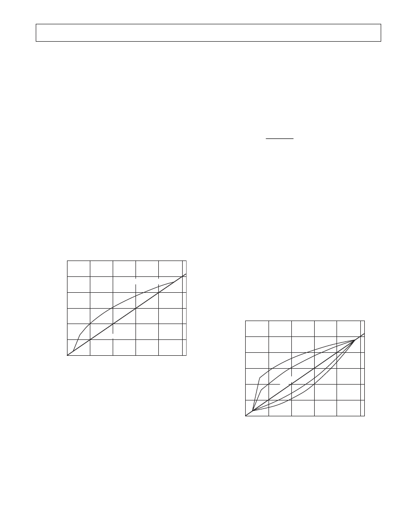
SIGNAL INPUT
G
SIGNAL OUTPUT
GAMMA CORRECTION BLOCK OUTPUT TO A RAMP INPUT
Figure 32. Signal Input (Ramp) and Signal Output
for Gamma 0.5
For the length of 16 to 240, the gamma correction curve has to
be calculated as follows:
=
y
x
where:
y
= gamma corrected output
x
= linear input signal
= gamma power factor
To program the gamma correction registers, the seven values for
y
have to be calculated using the following formula:
y
x
n
n
=
(
)
×
(
)
+
(
)
16
240
16
240
16
16
where:
x
(n–16)
= Value for x along x-axis at points
n
= 24, 32, 48, 64, 80, 96, 128, 160, 192 or 224
y
n
= Value for y along the y-axis, which has to be written into
the gamma correction register
For example:
y
24
= [(8 / 224)
0.5
×
224] + 16 = 58
*
y
32
= [16 / 224)
0.5
×
224] + 16 = 76
*
y
48
= [(32 / 224)
0.5
×
224] + 16 = 101
*
y
64
= [(48 / 224)
0.5
×
224] + 16 =120
*
y
80
= [(64 / 224)
0.5
×
224] + 16 =136
*
y
96
= [(80 / 224)
0.5
×
224] + 16 = 150
*
y
128
= [(112 / 224)
0.5
×
224] + 16 = 174
*
y
160
= [(144 / 224)
0.5
×
224] + 16 = 195
*
y
192
= [(176 / 224)
0.5
×
224] + 16 = 214
*
y
224
= [(208 / 224)
0.5
×
224] + 16 = 232
*
*
rounded to the nearest integer
The gamma curves in Figure 32 and 33 are examples only; any
user defined curve is acceptable in the range of 16–240.
LOCATION
00
50
100
150
200
250
300
50
100
150
200
250
G
GAMMA CORRECTION BLOCK TO A RAMP INPUT FOR
VARIOUS GAMMA VALUES
0.3
0.5
1.5
1.8
SGNALINPUT
Figure 33. Signal Input (Ramp) and Selectable
Gamma Output Curves
相關(guān)PDF資料 |
PDF描述 |
|---|---|
| ADV7330KST | Multiformat 11-Bit Triple DAC Video Encoder |
| ADXL321 | Small and Thin 18 g Accelerometer |
| ADXL321EB | Small and Thin 18 g Accelerometer |
| ADXL321JCP | Small and Thin 18 g Accelerometer |
| ADXL321JCP-REEL | Small and Thin 18 g Accelerometer |
相關(guān)代理商/技術(shù)參數(shù) |
參數(shù)描述 |
|---|---|
| ADV73305502 | 制造商:LG Corporation 功能描述:FRAME ASSEMBLY |
| ADV73306701 | 制造商:LG Corporation 功能描述:Frame Assembly |
| ADV73306702 | 制造商:LG Corporation 功能描述:Frame Assembly |
| ADV73306703 | 制造商:LG Corporation 功能描述:Frame Assembly |
| ADV73306704 | 制造商:LG Corporation 功能描述:Frame Assembly |
發(fā)布緊急采購,3分鐘左右您將得到回復(fù)。