- 您現(xiàn)在的位置:買(mǎi)賣(mài)IC網(wǎng) > PDF目錄366891 > CR16HCT5VJE7Y Microcontroller PDF資料下載
參數(shù)資料
| 型號(hào): | CR16HCT5VJE7Y |
| 英文描述: | Microcontroller |
| 中文描述: | 微控制器 |
| 文件頁(yè)數(shù): | 149/157頁(yè) |
| 文件大小: | 1256K |
| 代理商: | CR16HCT5VJE7Y |
第1頁(yè)第2頁(yè)第3頁(yè)第4頁(yè)第5頁(yè)第6頁(yè)第7頁(yè)第8頁(yè)第9頁(yè)第10頁(yè)第11頁(yè)第12頁(yè)第13頁(yè)第14頁(yè)第15頁(yè)第16頁(yè)第17頁(yè)第18頁(yè)第19頁(yè)第20頁(yè)第21頁(yè)第22頁(yè)第23頁(yè)第24頁(yè)第25頁(yè)第26頁(yè)第27頁(yè)第28頁(yè)第29頁(yè)第30頁(yè)第31頁(yè)第32頁(yè)第33頁(yè)第34頁(yè)第35頁(yè)第36頁(yè)第37頁(yè)第38頁(yè)第39頁(yè)第40頁(yè)第41頁(yè)第42頁(yè)第43頁(yè)第44頁(yè)第45頁(yè)第46頁(yè)第47頁(yè)第48頁(yè)第49頁(yè)第50頁(yè)第51頁(yè)第52頁(yè)第53頁(yè)第54頁(yè)第55頁(yè)第56頁(yè)第57頁(yè)第58頁(yè)第59頁(yè)第60頁(yè)第61頁(yè)第62頁(yè)第63頁(yè)第64頁(yè)第65頁(yè)第66頁(yè)第67頁(yè)第68頁(yè)第69頁(yè)第70頁(yè)第71頁(yè)第72頁(yè)第73頁(yè)第74頁(yè)第75頁(yè)第76頁(yè)第77頁(yè)第78頁(yè)第79頁(yè)第80頁(yè)第81頁(yè)第82頁(yè)第83頁(yè)第84頁(yè)第85頁(yè)第86頁(yè)第87頁(yè)第88頁(yè)第89頁(yè)第90頁(yè)第91頁(yè)第92頁(yè)第93頁(yè)第94頁(yè)第95頁(yè)第96頁(yè)第97頁(yè)第98頁(yè)第99頁(yè)第100頁(yè)第101頁(yè)第102頁(yè)第103頁(yè)第104頁(yè)第105頁(yè)第106頁(yè)第107頁(yè)第108頁(yè)第109頁(yè)第110頁(yè)第111頁(yè)第112頁(yè)第113頁(yè)第114頁(yè)第115頁(yè)第116頁(yè)第117頁(yè)第118頁(yè)第119頁(yè)第120頁(yè)第121頁(yè)第122頁(yè)第123頁(yè)第124頁(yè)第125頁(yè)第126頁(yè)第127頁(yè)第128頁(yè)第129頁(yè)第130頁(yè)第131頁(yè)第132頁(yè)第133頁(yè)第134頁(yè)第135頁(yè)第136頁(yè)第137頁(yè)第138頁(yè)第139頁(yè)第140頁(yè)第141頁(yè)第142頁(yè)第143頁(yè)第144頁(yè)第145頁(yè)第146頁(yè)第147頁(yè)第148頁(yè)當(dāng)前第149頁(yè)第150頁(yè)第151頁(yè)第152頁(yè)第153頁(yè)第154頁(yè)第155頁(yè)第156頁(yè)第157頁(yè)

149
www.national.com
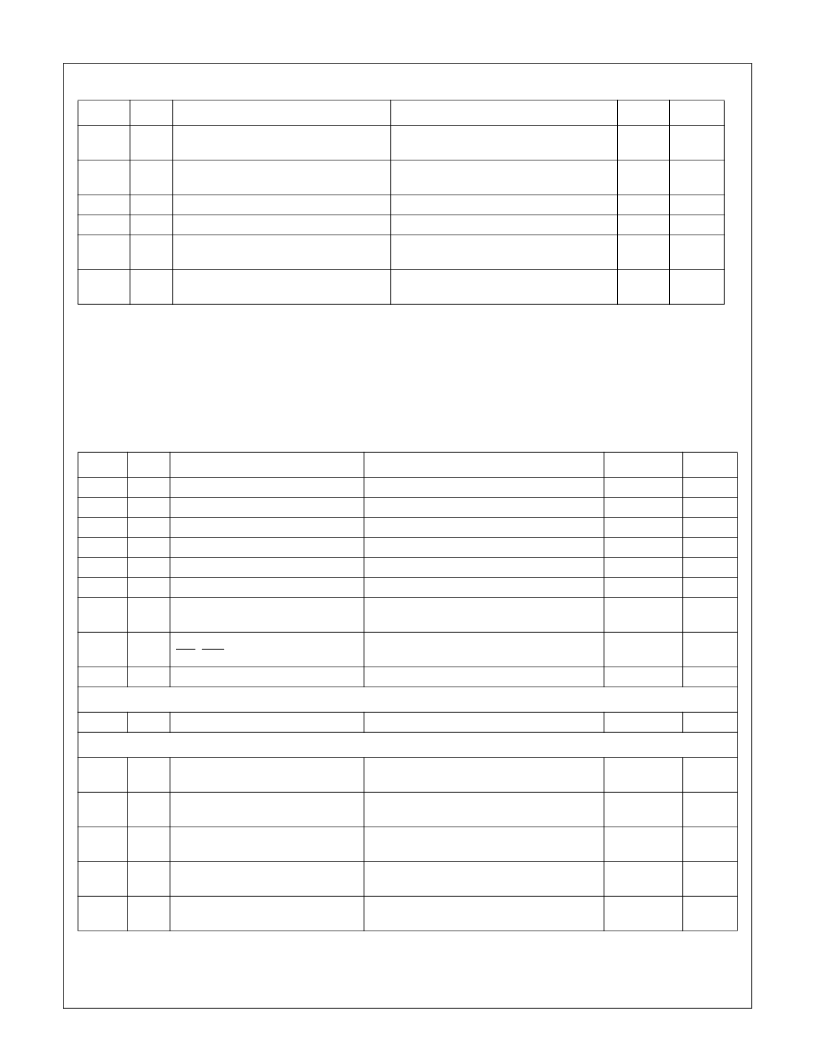
t
SCLlowo
91
SCL low time
After SCL F.E.
K*t
CLK
-
1
e
K*t
CLK
-
1
e
t
SCLhigho
91
SCL high time
After SCL R.E.
t
SDAfo
t
SDAro
88
88
SDA signal Fall time
SDA signal Rise time
300
-
t
SDAho
91
SDA hold time
After SCL F.E.
7*t
CLK
-
t
SCLfo
t
SDAvo
91
SDA valid time
After SCL F.E.
7*tCLK+
tRD
a. Tclk is the actual clock period of the CPU clock used in the system.
The value of Tclk is system dependent.
The maximum cycle time of 64000ns is for Power Save mode; in active mode, the maximum cycle time is limited to 250ns by
the high frequency oscillator.
b. Guaranteed by design, but not fully tested.
c. Assuming signal’s capacitance up to 400pF.
d. Depends on the signal’s capacitance and the pull-up value. Must be less than 1ms.
e. K is as defined in ACBCTL2.SCLFRQ.
Table 46
Input Signal Requirements
Symbol Figure
Description
Reference
Min (ns)
Max (ns)
t
X1p
t
X1h
t
X1l
t
X2p
t
X2h
t
X2l
77
77
77
77
77
77
X1 period
X1 high time, external clock
X1 low time, external clock
X2 period
a
X2 high time, external clock
X2 low time, external clock
Input setup time
ISE
Input hold time
ISE, NMI, RXD1, RXD2
Reset time
R.E. X1 to next R.E. X1
At 2V level (Both Edges)
At 0.8V level (Both Edges)
R.E. X2 to next R.E. X2
At 2V level (both edges)
At 0.8V level (both edges)
Before R.E. CLK
40
0.5 Tclk - 4
0.5 Tclk - 4
10,000
0.5 Tclk - 500
0.5 Tclk - 500
t
Is
81
12
t
Ih
81
After R.E. CLK
0
t
RST
82
Reset active to reset end
4Tclk
Input Signals
Input Pulse Width
1*Tclk+13
USART Input Signals
t
Is
80
Input setup time
RXDn (asynchronous mode)
Input hold time
RXDn (asynchronous mode)
CKXn input period
(synchronous mode)
RDXn setup time
(synchronous mode)
RDXn hold time
(synchronous mode)
Before R.E. CLK
12
t
Ih
80
After R.E. CLK
0
t
CLKX
81
200
t
RXS
81
Before F.E. CKX in synchronous mode
4
t
RXH
81
After F.E. CKX in synchronous mode
2
Table 45
Output Signals
Symbol Figure
Description
Reference
Min (ns) Max (ns)
相關(guān)PDF資料 |
PDF描述 |
|---|---|
| CR16HCT5VJE8Y | Microcontroller |
| CR16HCT5VJE9Y | Microcontroller |
| CR16HCT9 | |
| CR16HCT9VJE7 | Microcontroller |
| CR16HCT9VJE7Y | Microcontroller |
相關(guān)代理商/技術(shù)參數(shù) |
參數(shù)描述 |
|---|---|
| CR16HCT5VJE8Y | 制造商:未知廠家 制造商全稱:未知廠家 功能描述:Microcontroller |
| CR16HCT5VJE9Y | 制造商:未知廠家 制造商全稱:未知廠家 功能描述:Microcontroller |
| CR16HCT5VJEXY | 制造商:NSC 制造商全稱:National Semiconductor 功能描述:CR16MCT9/CR16MCT5/CR16HCT9/CR16HCT5 16-Bit Reprogrammable/ROM Microcontroller |
| CR16HCT9 | 制造商:NSC 制造商全稱:National Semiconductor 功能描述:CR16MCT9/CR16MCT5/CR16HCT9/CR16HCT5 16-Bit Reprogrammable/ROM Microcontroller |
| CR16HCT9VJE7 | 制造商:未知廠家 制造商全稱:未知廠家 功能描述:Microcontroller |
發(fā)布緊急采購(gòu),3分鐘左右您將得到回復(fù)。