參數資料
| 型號: | ISLA214S50IR1Z |
| 廠商: | Intersil |
| 文件頁數: | 40/41頁 |
| 文件大小: | 0K |
| 描述: | IC ADC |
| 標準包裝: | 1 |
| 系列: | * |
第1頁第2頁第3頁第4頁第5頁第6頁第7頁第8頁第9頁第10頁第11頁第12頁第13頁第14頁第15頁第16頁第17頁第18頁第19頁第20頁第21頁第22頁第23頁第24頁第25頁第26頁第27頁第28頁第29頁第30頁第31頁第32頁第33頁第34頁第35頁第36頁第37頁第38頁第39頁當前第40頁第41頁

ISLA214S50
8
FN7973.2
April 25, 2013
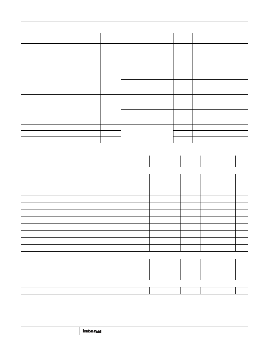
Largest Interleave Spur
fIN = 10MHz to 240MHz, Active
Run State enabled, in Track Mode
-99
dBc
fIN = 10MHz to 240MHz, Active
Run State enabled and previously
settled, in Hold Mode
-80
dBc
fIN = 260MHz to 490MHz, Active
Run State enabled, in Track Mode
-95
dBc
fIN = 260MHz to 490MHz, Active
Run State enabled and previously
settled, in Hold Mode
-70
dBc
Total Interleave Spurious Power
Active Run State enabled, in
Track Mode, fIN is a broadband
signal in the 1st Nyquist zone
-85
dBc
Active Run State enabled, in
Track Mode, fIN is a broadband
signal in the 2nd Nyquist zone
-75
dBc
Sample Time Mismatch Between Unit ADCs
Active Run State enabled, in
Track Mode
25
fs
Gain Mismatch Between Unit ADCs
0.02
%FS
Offset Mismatch Between Unit ADCs
1mV
I2E Specifications Boldface limits apply over the operating temperature range, -40°C to +85°C. (Continued)
PARAMETER
SYMBOL
CONDITIONS
MIN
(Note 6)
TYP
MAX
(Note 6)
UNITS
Digital Specifications Boldface limits apply over the operating temperature range, -40°C to +85°C.
PARAMETER
SYMBOL
CONDITIONS
MIN
(Note 6)
TYP
MAX
(Note 6) UNITS
CMOS INPUTS
Input Current High (RESETN)
IIH
VIN = 1.8V
1
10
A
Input Current Low (RESETN)
IIL
VIN = 0V
-25
-12
-7
A
Input Current High (SDIO, SCL, SDA SCLK)
IIH
VIN = 1.8V
4
12
A
Input Current Low (SDIO, SCL, SDA SCLK)
IIL
VIN = 0V
-600
-400
-300
A
Input Current High (CSB)
IIH
VIN = 1.8V
40
52
70
A
Input Current Low (CSB)
IIL
VIN = 0V
1
10
A
Input Voltage High (SDIO, RESETN)
VIH
1.17
V
Input Voltage Low (SDIO, RESETN)
VIL
0.63
V
Input Current High (NAPSLP, CLKDIV) (Note 11)
IIH
19
25
30
A
Input Current Low (NAPSLP, CLKDIV)
IIL
--30
-25
-19
A
Input Capacitance
CDI
4pF
LVDS INPUTS (SYNCP, SYNCN)
Input Common Mode Range
VICM
825
1575
mV
Input Differential Swing (peak-to-peak, single-ended)
VID
250
450
mV
Input Pull-up and Pull-down Resistance
RIpu
100
k
CML OUTPUTS
Output Common Mode Voltage
1.14
mV
相關PDF資料 |
PDF描述 |
|---|---|
| ISLA222P13IRZ | IC ADC 12BIT SRL/SPI 72QFN |
| ISLA224S25IR1Z | IC ADC |
| KAD2708C-27Q68 | IC ADC 8BIT 275MSPS PAR 68-QFN |
| KAD2708L-27Q68 | IC ADC 8BIT 275MSPS PAR 68-QFN |
| KAD2710C-27Q68 | IC ADC 10BIT 275MSPS PAR 68-QFN |
相關代理商/技術參數 |
參數描述 |
|---|---|
| ISLA214S50IR48EV1Z | 制造商:Intersil Corporation 功能描述:ISLA214S50IRZ EVALUATION BOARD 1 48LD QFN ROHS COMPLIANT - Bulk 制造商:Intersil Corporation 功能描述:ISLA214S50IRZ EVALUATION BOARD 1 48LD QFN ROHS COMPLIANT |
| ISLA216IR72EV1Z | 制造商:Intersil Corporation 功能描述:ISLA216IR72 EVAL BOARD - 72 LD QFN - SINGLE 16-BIT 250MSPS U - Bulk 制造商:Intersil Corporation 功能描述:EVAL BOARD FOR ISLA216IR72 制造商:Intersil Corporation 功能描述:EVAL BOARD ADC ISLA216P 制造商:Intersil Corporation 功能描述:EVAL BOARD, ADC, ISLA216P 制造商:Intersil 功能描述:ISLA216IR72 EVALRD 72LD SNGL 16-BIT 制造商:Intersil Corporation 功能描述:EVAL BOARD, ADC, ISLA216P; Silicon Manufacturer:Intersil; Silicon Core Number:ISLA216P; Kit Application Type:Data Converter; Application Sub Type:ADC; Kit Contents:Evaluation Board for ISLA216P ADC |
| ISLA216P | 制造商:INTERSIL 制造商全稱:Intersil Corporation 功能描述:16-Bit, 250MSPS/200MSPS/130MSPS ADC |
| ISLA216P_1104 | 制造商:INTERSIL 制造商全稱:Intersil Corporation 功能描述:16-Bit, 250MSPS/200MSPS/130MSPS ADC |
| ISLA216P13 | 制造商:INTERSIL 制造商全稱:Intersil Corporation 功能描述:12-Bit, 500MSPS ADC Programmable Built-in Test Patterns |
發(fā)布緊急采購,3分鐘左右您將得到回復。