- 您現(xiàn)在的位置:買(mǎi)賣(mài)IC網(wǎng) > PDF目錄377968 > MK68901 (意法半導(dǎo)體) Multifunction Peripheral(多功能外圍電路) PDF資料下載
參數(shù)資料
| 型號(hào): | MK68901 |
| 廠商: | 意法半導(dǎo)體 |
| 英文描述: | Multifunction Peripheral(多功能外圍電路) |
| 中文描述: | 多功能外圍(多功能外圍電路) |
| 文件頁(yè)數(shù): | 10/33頁(yè) |
| 文件大小: | 313K |
| 代理商: | MK68901 |
第1頁(yè)第2頁(yè)第3頁(yè)第4頁(yè)第5頁(yè)第6頁(yè)第7頁(yè)第8頁(yè)第9頁(yè)當(dāng)前第10頁(yè)第11頁(yè)第12頁(yè)第13頁(yè)第14頁(yè)第15頁(yè)第16頁(yè)第17頁(yè)第18頁(yè)第19頁(yè)第20頁(yè)第21頁(yè)第22頁(yè)第23頁(yè)第24頁(yè)第25頁(yè)第26頁(yè)第27頁(yè)第28頁(yè)第29頁(yè)第30頁(yè)第31頁(yè)第32頁(yè)第33頁(yè)

In the delay mode, the prescaler is always active.
A count pulse will be applied to the main timer unit
each time the prescribed number of timer clock cy-
cles haselapsed. Thus, if theprescaler is program-
med to divide by ten, a count pulse will be applied
to the main counter every ten cycles of the timer
clock.
Each timeacount pulseisapplied tothe maincoun-
ter, it willdecrement its contents. The main counter
is initially loaded by writingto theTimer Data Regis-
ter. Each count pulse will cause the current count to
decrement. When thetimerhas decremented down
to ”01” , the next count pulse will not cause it to de-
crement to ”00”. Instead, the next count pulse will
cause the timer to be reloaded from the Timer Data
Register.Additionally, a ”Timeout”pulse willbepro-
duced. This Time Out pulse is coupled to the timer
interrupt channel, and, ifthat channel isenabled, an
interrupt willbe produced. TheTime Outpulse is al-
so coupled to the timeroutput pin and will cause the
pin to change states. The output will remain in this
newstateuntilthenextTimeOutpulse occurs.Thus
the output will complete one full cycle for each two
Time Out pulses.
If, for example, the prescaler were programmed to
divideby ten,and the TimerDataRegister wereloa-
ded with 100 (decimal), themain counter would de-
crement once for everytencyclesofthetimerclock.
ATimeOutpulsewilloccur(henceaninterrupt ifthat
channel is enabled) every 1000 cycles of the timer
clock, and the timer outputwill complete one fullcy-
cleevery 2000 cycles of thetimer clock.
The main counter is an 8-bit binary down counter. It
maybe readat any time by reading theTimer Data
Register. The information read is the information
last clockedintothetimer read registerwhenthe DS
pinhad lastgone high prior tothecurrent readcycle.
When written,data isloaded intotheTimerDataRe-
gister, and the main counter, ifthe timer is stopped.
If the Timer Data Register is written while the timer
is running, the newword is notloaded into the timer
until it counts through H”01”. However, if the timer
iswritten while itis counting through H”01”, an inde-
terminatevalue willbe writteninto thetimer constant
register. This may becircumvented byensuring that
the data register is not written when the count is
H”01”.
If the main counter is loaded with ”01”, a Time Out
Pulse will occur every time the prescaler presents
a count pulse to the main counter. If loaded with
”00”, a Time Out pulse will occur every 256 count
pulses.
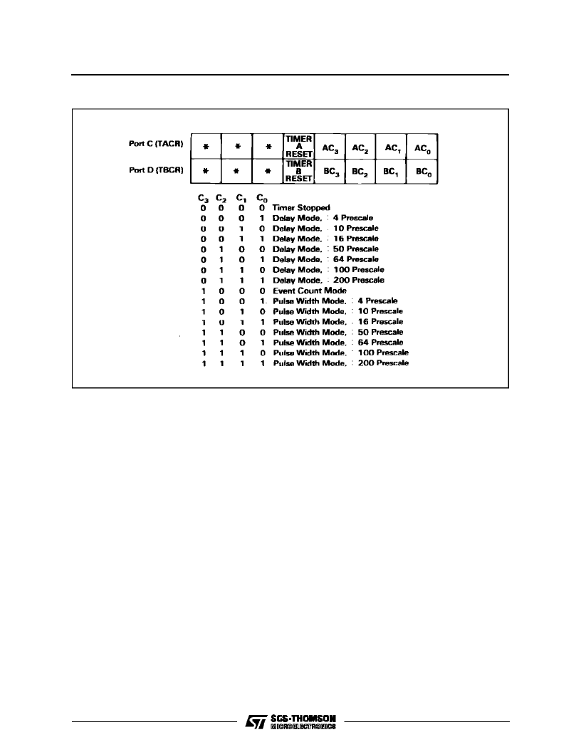
Figure 12 :
Timer A and B Control Registers.
*
Unused bits : read as zeros.
V000359
MK68901
10/33
相關(guān)PDF資料 |
PDF描述 |
|---|---|
| MK70110 | Bluetooth? Module |
| MK70120 | Bluetooth? Module |
| ML2003IQ | Logarithmic Gain/Attenuator |
| ML2003CP | Logarithmic Gain/Attenuator |
| ML2003CQ | Logarithmic Gain/Attenuator |
相關(guān)代理商/技術(shù)參數(shù) |
參數(shù)描述 |
|---|---|
| MK68901N-05 | 制造商:STMicroelectronics 功能描述:PERIPHERAL (MULTIFUNCTION) CONTROLLER, 48 Pin, DIP |
| MK6-8-B | 制造商:MEDER Electronic 功能描述:REED SENSOR 制造商:MEDER Electronic 功能描述:REED SENSOR; Sensing Range Max:15mm; Supply Current:500mA; Operating Temperature Min:-20C; Operating Temperature Max:85C; SVHC:No SVHC (19-Dec-2012); Breakdown Voltage Vbr:230VDC; Contact Configuration:1 Form A; Contact Current AC ;RoHS Compliant: Yes |
| MK-6-8-BV50590 | 制造商:MEDER Electronic 功能描述: |
| MK6-8-H | 制造商:MEDER Electronic 功能描述:REED SENSOR 制造商:MEDER Electronic 功能描述:REED SENSOR; Sensing Range Max:20mm; Supply Current:500mA; Operating Temperature Min:-20C; Operating Temperature Max:85C; SVHC:No SVHC (19-Dec-2012); Breakdown Voltage Vbr:230VDC; Contact Configuration:1 Form A; Contact Current AC ;RoHS Compliant: Yes |
| MK6-8-K | 制造商:MEDER Electronic 功能描述: |
發(fā)布緊急采購(gòu),3分鐘左右您將得到回復(fù)。