- 您現(xiàn)在的位置:買賣IC網(wǎng) > PDF目錄385942 > TNET3001 (Texas Instruments, Inc.) SONET STS-1 Overhead Terminator(SONET STS-1附加終端) PDF資料下載
參數(shù)資料
| 型號(hào): | TNET3001 |
| 廠商: | Texas Instruments, Inc. |
| 英文描述: | SONET STS-1 Overhead Terminator(SONET STS-1附加終端) |
| 中文描述: | SONET的STS - 1的開銷終結(jié)者(SONET的STS - 1的附加終端) |
| 文件頁(yè)數(shù): | 39/49頁(yè) |
| 文件大小: | 1090K |
| 代理商: | TNET3001 |
第1頁(yè)第2頁(yè)第3頁(yè)第4頁(yè)第5頁(yè)第6頁(yè)第7頁(yè)第8頁(yè)第9頁(yè)第10頁(yè)第11頁(yè)第12頁(yè)第13頁(yè)第14頁(yè)第15頁(yè)第16頁(yè)第17頁(yè)第18頁(yè)第19頁(yè)第20頁(yè)第21頁(yè)第22頁(yè)第23頁(yè)第24頁(yè)第25頁(yè)第26頁(yè)第27頁(yè)第28頁(yè)第29頁(yè)第30頁(yè)第31頁(yè)第32頁(yè)第33頁(yè)第34頁(yè)第35頁(yè)第36頁(yè)第37頁(yè)第38頁(yè)當(dāng)前第39頁(yè)第40頁(yè)第41頁(yè)第42頁(yè)第43頁(yè)第44頁(yè)第45頁(yè)第46頁(yè)第47頁(yè)第48頁(yè)第49頁(yè)
TNETS3001
SONET STS-1 OVERHEAD TERMINATOR
SDNS007B – OCTOBER 1993 – REVISED JUNE 1995
39
POST OFFICE BOX 655303
DALLAS, TEXAS 75265
PRINCIPLES OF OPERATION
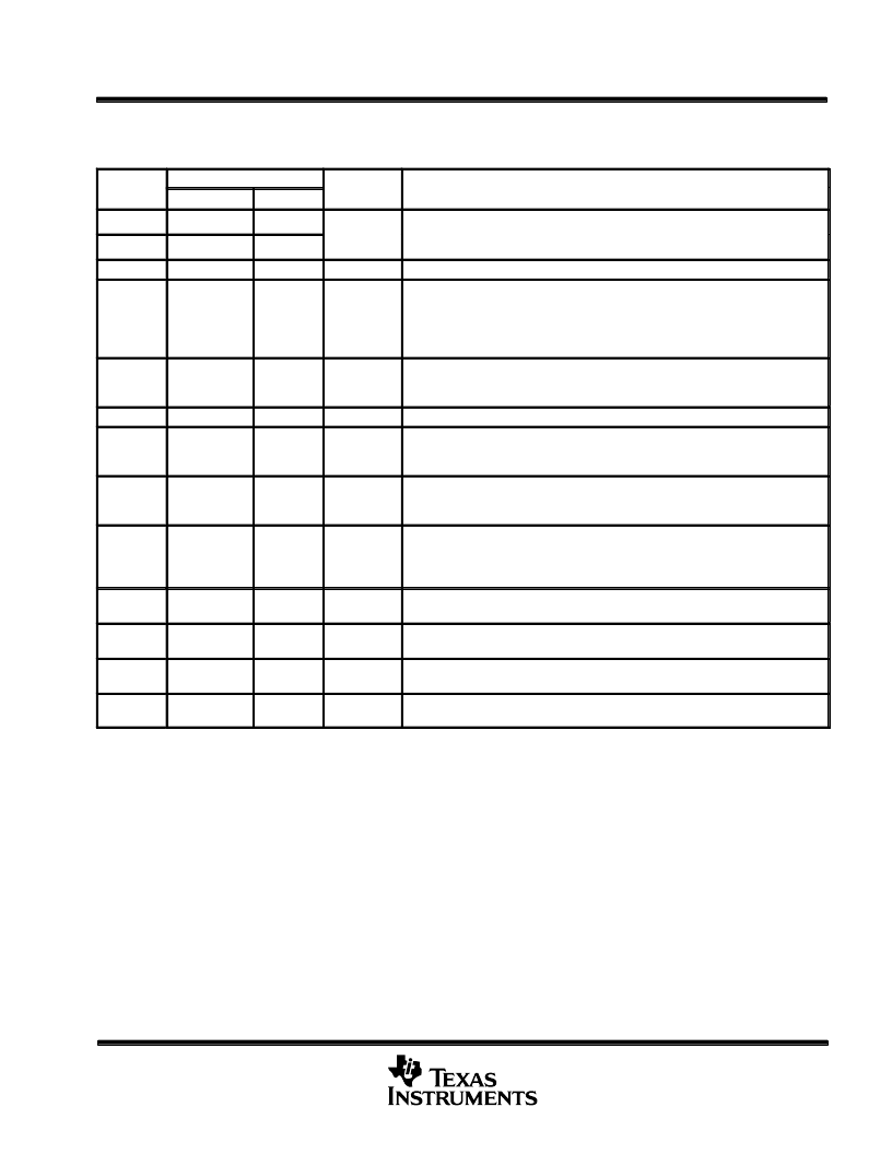
transmit terminal- and line-overhead byte RAM locations
SYMBOL
ADDRESS (hex)
CONTROL
BIT
DESCRIPTION
INCOMING
INSERT
A1
116
136
Framing pattern. The outgoing A1 and A2 bytes are stored in insert locations and
automatically inserted into the outgoing line data The A1 and A2 bytes are
automatically inserted into the outgoing line data. The A1 and A2 bytes are
regenerated every frame when the control bit TRFRM = 1.
A2
117
137
C1
11C
13C
TRC1
STS-1 signal identifier. Normal operation.
B1
114
134
149
TRERR
Section BIP-8 parity/error mask. B1 errors are added to the transmit B1
counter. The outgoing B1 BIP-8 parity is recalculated and stored in insert
location 134. In the STS-1 mode, the recalculated B1 is XORed with the B1 error
mask from location 149 before transmission. In the STS-N mode, the B1 error mask
from location 149 is transmitted.
E1
118
138
TRE1
TE2A§
TA2E§
Section-orderwire byte
.
The E2 byte from the orderwire interface is stored in the
insert location. The E1 byte is optionally reused for AIS communication
between TNETS3001s.
F1
11D
13D
TRF1
Section-user byte. Normal operation.
D1
D2
D3
105
106
107
125
126
127
TRSD
Section data-communication channel. The section-datacom bytes, D1 – D3, from
the section-datacom interface are stored in the insert location.
H1
H2
H3
111
112
113
133
Payload-pointer and pointer-action bytes
.
The TNETS3001 automatically
recalculates the outgoing pointer. The H3 byte is inserted from RAM location 133.
B2
115
135
151
TRERR
Line BIP-8 bit parity. The B2 errors are added to the transmit B2 counter. The
outgoing B2 BIP-8 parity is recalculated and stored in the insert location 135. The
recalculated B2 is XORed with the B2 error mask from location 151 before
transmission.
K1
K2
11E
11F
13E
13F
TRAPS
EXAPS
Automatic-protection-switching bytes. If EXAPS is set, the APS bytes from the
orderwire interface are stored in the insert RAM locations.
D4–D12
108–110
128–130
TRLD
Line data-communication channel. The line-datacom bytes, D4–D12, from the
section-datacom interface are stored in the insert location.
E2
119
139
TRE2
Line-orderwire byte. The E2 byte from the orderwire interface is stored in the insert
location.
Z1
Z2
11A
11B
13A
13B
TRZ1
TRZ2
Growth bytes. Normal operation.
The insert bytes are multiplexed into the line data when the corresponding control bit is set. If used, the microprocessor initializes the insert
locations.
In SPE-only modes, the incoming terminal data has these bytes as an all-zeros pattern.
§The E1 byte can be used for AIS transmission. All ones in the E1 byte indicates an AIS condition; all zeros indicates a non-AIS condition. If the
control bit TE2A is set, the TNETS3001 interprets the incoming E1 byte for AIS information. When the control bit TA2E is set, the line E1 byte
carries AIS information.
If TRERR is set, the error masks are reset after transmission; otherwise, error is transmitted continuously.
P
相關(guān)PDF資料 |
PDF描述 |
|---|---|
| TNETA1530 | 155.52-MHz Clock-Generation Device(155.52-MHz時(shí)鐘發(fā)生裝置) |
| TNETA1531 | 155.52-MHz Clock-Generation Device(155.52-MHz時(shí)鐘發(fā)生裝置) |
| TNETA1545 | Dual Differential PSEUDO-ECL to ECL Transistors and Dual Differential ECL to PSEUDO-ECL Transistors(雙差分ECL TO PSEUDO-ECL轉(zhuǎn)換器和ECL-PSEUDO TO ECL轉(zhuǎn)換器) |
| TNETA1555 | 155.52-Mbit/S Clock-Recovery Device(155.52-MBIT/S時(shí)鐘恢復(fù)裝置) |
| TNETA1556 | 155.52-Mbit/S Clock-Recovery Device(155.52-MBIT/S時(shí)鐘恢復(fù)裝置) |
相關(guān)代理商/技術(shù)參數(shù) |
參數(shù)描述 |
|---|---|
| TNETA1500A | 制造商:TI 制造商全稱:Texas Instruments 功能描述:155.52-MBIT/S SONET/SDH ATM RECEIVER/TRANSMITTER |
| TNETA1500APCM | 制造商:Texas Instruments 功能描述:TRANSCEIVER, 144 Pin Plastic QFP |
| TNETA1500APGE | 制造商:Rochester Electronics LLC 功能描述:- Bulk |
| TNETA1500PCM | 制造商:TI 制造商全稱:Texas Instruments 功能描述:155.52-MBIT/S SONET/SDH ATM RECEIVER/TRANSMITTER |
| TNETA1530DW | 制造商:未知廠家 制造商全稱:未知廠家 功能描述:Miscellaneous Clock Generator |
發(fā)布緊急采購(gòu),3分鐘左右您將得到回復(fù)。