- 您現(xiàn)在的位置:買賣IC網 > PDF目錄366034 > TTRN0110G ATM MULTIPLEXER|BGA|198PIN|CERAMIC PDF資料下載
參數(shù)資料
| 型號: | TTRN0110G |
| 英文描述: | ATM MULTIPLEXER|BGA|198PIN|CERAMIC |
| 中文描述: | ATM多路復用器|的BGA | 198PIN |陶瓷 |
| 文件頁數(shù): | 9/30頁 |
| 文件大小: | 578K |
| 代理商: | TTRN0110G |
第1頁第2頁第3頁第4頁第5頁第6頁第7頁第8頁當前第9頁第10頁第11頁第12頁第13頁第14頁第15頁第16頁第17頁第18頁第19頁第20頁第21頁第22頁第23頁第24頁第25頁第26頁第27頁第28頁第29頁第30頁

Agere Systems Inc.
9
Data Sheet
March 29, 2002
10 Gbits/s Clock Synthesizer, 16:1 Data Multiplexer
TTRN0110G
Ball Information
(continued)
Ball Description
(continued)
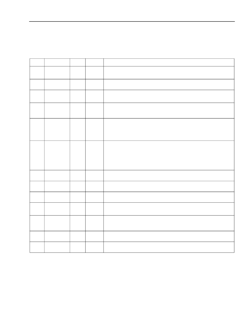
Table 3. Ball Descriptions—622.08 Mbits/s and Related Signals
(continued)
Ball
Symbol
*
* Differential pairs are indicated by P and N suffixes. For nondifferential pins, N at the end of the symbol name designates active-low.
I = input, O = output. I
indicates an internal pull-up resistor on this pin. Id indicates an internal pull-down resistor on this pin. It = an
internal termination resistance of 50
to V
CCD
on this pin.
Type
Level
Name/Description
R13
P13
CK622P
CK622N
O
LVDS
Clock Output (622 MHz).
622 MHz differential clock output.
Note:
This clock frequency will scale when operating at different rates.
Phase Adjust.
Adjusts phase of CK622 in 90 degree steps.
M15
L14
R11
P11
PHADJ[0]
PHADJ[1]
CK155P
CK155N
I
d
CMOS
O
LVDS
Clock Output (155 MHz).
155 MHz differential clock output.
Note:
This clock frequency will scale when operating at different rates.
Enable CK155P/N Clock Output (Active-Low).
0 = CK155P/N buffer enabled.
1 or no connection = CK155P/N buffer powered off.
Parallel Input Clock (622 MHz 311 MHz).
622 MHz or 311 MHz
differential clock input used to register parallel data when using forward
directional clocking mode.
Note:
This clock frequency will scale when operating at different rates.
Clock Mode Select.
Selects clocking method for data transfer mode.
[0] [1]
0 0 = Forward directional clocking mode (622 MHz).
0 1 = Forward directional clocking mode (311 MHz).
1 0 = Contraclocking mode.
1 1 or no connections = Clockless mode.
Loss of Lock (Active-Low).
0 = PLL out of lock.
External Center.
Centers the pointers in the parallel data storage
element. Connected to OVRFLW for fastest FIFO overrun recovery.
Data Storage Overflow.
Indicates (active-high) when an overflow has
occurred in the parallel data storage element.
Reference Clock Input (622.08 MHz or 155.52 MHz).
Note:
This clock frequency will scale when operating at different rates.
Reference Clock Frequency.
Selects frequency of REFCLKP/N.
0 = 155 MHz.
1 or no connection = 622 MHz.
Analog
Loop Filter PLL.
Connect LFP and LFN to loop filter (see Table 6 on
page 11).
Analog
Resistor Reference LVDS.
LVDS bias reference resistor. Connect a
1.5 k
resistor to V
CCD
.
K13
ENCK155N
I
u
CMOS
R12
P12
PICLKP
PICLKN
I
LVDS
H15
J15
CLKMOD[0]
CLKMOD[1]
I
u
CMOS
G12
LCKLOSSN
O
CMOS
K15
EXTCNTR
I
d
CMOS
J14
OVRFLW
O
CMOS
N14
M14
REFCLKP
REFCLKN
I
LVDS
L15
REFFREQ
I
u
CMOS
F15
E15
F12
LFP
LFN
I
RREFLVDS
I
相關PDF資料 |
PDF描述 |
|---|---|
| TTSAL | Crystal Oscillator |
| TU0425W-20 | TUBING 4MM WHITE 20M |
| TCU0425B-1 | Transient Voltage Suppressor Diodes |
| TCU0425B-2 | Transient Voltage Suppressor Diodes |
| TCU0425B-3 | Transient Voltage Suppressor Diodes |
相關代理商/技術參數(shù) |
參數(shù)描述 |
|---|---|
| TTRN012G5 | 制造商:AGERE 制造商全稱:AGERE 功能描述:TTRN012G5 (2.5 Gbits/s) and TTRN012G7 (2.5 Gbits/s and 2.7 Gbits/s) Clock Synthesizer, 16:1 Data Multiplexer |
| TTRN012G53XE1 | 制造商:AGERE 制造商全稱:AGERE 功能描述:TTRN012G5 (2.5 Gbits/s) and TTRN012G7 (2.5 Gbits/s and 2.7 Gbits/s) Clock Synthesizer, 16:1 Data Multiplexer |
| TTRN012G7 | 制造商:AGERE 制造商全稱:AGERE 功能描述:TTRN012G5 (2.5 Gbits/s) and TTRN012G7 (2.5 Gbits/s and 2.7 Gbits/s) Clock Synthesizer, 16:1 Data Multiplexer |
| TTRN012G73XE1 | 制造商:AGERE 制造商全稱:AGERE 功能描述:TTRN012G5 (2.5 Gbits/s) and TTRN012G7 (2.5 Gbits/s and 2.7 Gbits/s) Clock Synthesizer, 16:1 Data Multiplexer |
| TTR-RED | 功能描述:打印機 Ribbon, Resin, 4.33" W x 299’ L, for use RoHS:否 制造商:Seiko Instruments 產品:Printer 電源電壓: 每行點數(shù):9 x 320 打印速度:52.5 cps, 80 cps 紙張寬度:112 mm |
發(fā)布緊急采購,3分鐘左右您將得到回復。