- 您現(xiàn)在的位置:買賣IC網(wǎng) > PDF目錄359412 > VPX3214 (Electronic Theatre Controls, Inc.) Video Pixel Decoders PDF資料下載
參數(shù)資料
| 型號: | VPX3214 |
| 廠商: | Electronic Theatre Controls, Inc. |
| 英文描述: | Video Pixel Decoders |
| 中文描述: | 視頻解碼器像素 |
| 文件頁數(shù): | 39/80頁 |
| 文件大?。?/td> | 752K |
| 代理商: | VPX3214 |
第1頁第2頁第3頁第4頁第5頁第6頁第7頁第8頁第9頁第10頁第11頁第12頁第13頁第14頁第15頁第16頁第17頁第18頁第19頁第20頁第21頁第22頁第23頁第24頁第25頁第26頁第27頁第28頁第29頁第30頁第31頁第32頁第33頁第34頁第35頁第36頁第37頁第38頁當(dāng)前第39頁第40頁第41頁第42頁第43頁第44頁第45頁第46頁第47頁第48頁第49頁第50頁第51頁第52頁第53頁第54頁第55頁第56頁第57頁第58頁第59頁第60頁第61頁第62頁第63頁第64頁第65頁第66頁第67頁第68頁第69頁第70頁第71頁第72頁第73頁第74頁第75頁第76頁第77頁第78頁第79頁第80頁
PRELIMINARY DATA SHEET
VPX 3220 A, VPX 216 B, VPX 3214 C
MICRONAS INTERMETALL
39
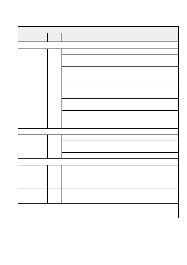
FP-Register Table
FP Reg.
Address
Number
of Bits
Mode
Function
Name
TV Standard – Read
TVstndRd
F3
12
r
Readable control register for managing the TV coding standard
bit [0] :
VACT suppress
0
1
enabled
suppressed
bit [1] :
Status of recognition routine
0
idle
1
running
bit [4:2] :
TV standard detected (by recognition routines)
x x x
see table above
bit [5] :
’No video’ flag
0
1
TV standard shown in bit [4:2] present
no video at selected input
bit [9:6] :
High score from video recognition routine (confidence level)
1 1 1 1
maximum confidence
0 0 0 0
minimum confidence
bit [10] :
TV line standard (for TV standard from bit [4:2] above)
0
525/60
1
625/50
bit [11] :
reserved
Vertical Standard
E7
12
w
Writeable control register for vertical locking
vsdt
bit [0]:
vertical standard lock enable
0
disabled
1
enabled
bit [11:1]
expected number of lines per field
Color Processing
1C
NTSC tint angle,
512 =
π
/4
tint
A0
ACC reference; also used to control color saturation
ACCref = 0:
ACC turned off
ACCref = 1:
minimal color saturation ie. color switched off
ACCref
A3
ACC multiplier value for SECAM Dr chroma component to adjust C
r
level
ACCr
A4
ACC multiplier value for SECAM Db chroma component to adjust C
b
level
ACCb
A8
amplitude color killer level
kilvl = 0:
killer disabled
kilvl
The control register modes are
– w: write/read register
– r:
read-only register
– A: register or register field has function only in VPX 3220 A
The mnemonics used in the Intermetall VPX demo software are given in the last column.
相關(guān)PDF資料 |
PDF描述 |
|---|---|
| VPX3214C | Video Pixel Decoders |
| VPX3224D | Video Pixel Decoders |
| VPX3224E | Video Pixel Decoders |
| VPX322XE | Video Pixel Decoders |
| VQ1000J | N-Channel Enhancement-Mode MOSFET Transistor(最小漏源擊穿電壓60V,夾斷電流0.225A的N溝道增強(qiáng)型MOSFET晶體管) |
相關(guān)代理商/技術(shù)參數(shù) |
參數(shù)描述 |
|---|---|
| VPX3214C | 制造商:未知廠家 制造商全稱:未知廠家 功能描述:Video Pixel Decoders |
| VPX3214C(PLCC44) | 制造商:未知廠家 制造商全稱:未知廠家 功能描述:Color Decoder Circuit |
| VPX3214C(QFP44) | 制造商:未知廠家 制造商全稱:未知廠家 功能描述:Color Decoder Circuit |
| VPX3216B | 制造商:未知廠家 制造商全稱:未知廠家 功能描述:Video Pixel Decoders |
| VPX3216B(PLCC44) | 制造商:未知廠家 制造商全稱:未知廠家 功能描述:Color Decoder Circuit |
發(fā)布緊急采購,3分鐘左右您將得到回復(fù)。