- 您現(xiàn)在的位置:買賣IC網(wǎng) > PDF目錄359412 > VPX322XE (MICRONAS SEMICONDUCTOR HOLDING AG) Video Pixel Decoders PDF資料下載
參數(shù)資料
| 型號: | VPX322XE |
| 廠商: | MICRONAS SEMICONDUCTOR HOLDING AG |
| 英文描述: | Video Pixel Decoders |
| 中文描述: | 視頻解碼器像素 |
| 文件頁數(shù): | 8/92頁 |
| 文件大小: | 567K |
| 代理商: | VPX322XE |
第1頁第2頁第3頁第4頁第5頁第6頁第7頁當前第8頁第9頁第10頁第11頁第12頁第13頁第14頁第15頁第16頁第17頁第18頁第19頁第20頁第21頁第22頁第23頁第24頁第25頁第26頁第27頁第28頁第29頁第30頁第31頁第32頁第33頁第34頁第35頁第36頁第37頁第38頁第39頁第40頁第41頁第42頁第43頁第44頁第45頁第46頁第47頁第48頁第49頁第50頁第51頁第52頁第53頁第54頁第55頁第56頁第57頁第58頁第59頁第60頁第61頁第62頁第63頁第64頁第65頁第66頁第67頁第68頁第69頁第70頁第71頁第72頁第73頁第74頁第75頁第76頁第77頁第78頁第79頁第80頁第81頁第82頁第83頁第84頁第85頁第86頁第87頁第88頁第89頁第90頁第91頁第92頁

ADVANCE INFORMATION
VPX 322xE
8
Micronas
2. Functional Description
The following sections provide an overview of the differ-
ent functional blocks within the VPX. Most of them are
controlled by the Fast Processor (
‘
FP
’
) embedded in the
decoder. For controlling, there are two classes of regis-
ters: I
2
C registers (directly addressable via I
2
C bus) and
FP-RAM registers (RAM memory of the FP; indirectly
addressable via I
2
C bus). For further information, see
section 2.15.1.
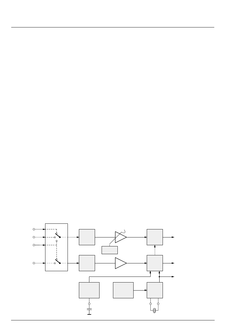
2.1. Analog Front-End
This block provides the analog interfaces to all video in-
puts and mainly carries out analog-to-digital conversion
for the following digital video processing. A block dia-
gram is given in Fig. 2
–
1.
Clamping, AGC, and clock DCO are digitally controlled.
The control loops are closed by the embedded proces-
sor.
2.1.1. Input Selector
Up to four analog inputs can be connected. Three inputs
(VIN1
–
3) are for input of composite video or S-VHS luma
signal. These inputs are clamped to the sync back porch
and are amplified by a variable gain amplifier. Two in-
puts, one dedicated (CIN) and one shared (VIN1), are
for connection of S-VHS carrier-chrominance signal.
The chrominance input is internally biased and has a
fixed gain amplifier.
2.1.2. Clamping
The composite video input signals are AC coupled to the
IC. The clamping voltage is stored on the coupling ca-
pacitors and is generated by digitally controlled current
sources. The clamping level is the back porch of the vid-
eo signal. S-VHS chroma is AC coupled. The input pin
is internally biased to the center of the ADC input range.
2.1.3. Automatic Gain Control
A digitally working automatic gain control adjusts the
magnitude of the selected baseband by +6/
–
4.5 dB in 64
logarithmic steps to the optimal range of the ADC.
2.1.4. Analog-to-Digital Converters
Two ADCs are provided to digitize the input signals.
Each converter runs with 20.25 MHz and has 8-bit reso-
lution. An integrated bandgap circuit generates the re-
quired reference voltages for the converters. The two
ADCs are of a 2-stage subranging type.
2.1.5. ADC Range
The ADC input range for the various input signals and
the digital representation is given in Table 2
–
1 and Fig.
2
–
2. The corresponding output signal levels of the
VPX 32xx are also shown.
2.1.6. Digitally Controlled Clock Oscillator
The clock generation is also a part of the analog front
end. The crystal oscillator is controlled digitally by the
FP; the clock frequency can be adjusted within
±
150 ppm.
Fig. 2
–
1:
Analog front-end
input mux
CVBS/Y
CVBS/Y
CVBS/Y/C
Chroma
VIN3
VIN2
VIN1
CIN
clamp
bias
reference
generation
gain
frequency
ADC
ADC
DCVO
±
150
ppm
digital CVBS or Luma
digital Chroma
system clocks
20.25 MHz
AGC
+6/
–
4.5 dB
相關(guān)PDF資料 |
PDF描述 |
|---|---|
| VQ1000J | N-Channel Enhancement-Mode MOSFET Transistor(最小漏源擊穿電壓60V,夾斷電流0.225A的N溝道增強型MOSFET晶體管) |
| VQ1000J | N-Channel 60-V (D-S) MOSFET |
| VQ1001J | Dual N-Channel 30-V (D-S) MOSFET with Schottky Diode |
| VQ1001J | N-Channel Enhancement-Mode MOSFET Transistor(最小漏源擊穿電壓30V,夾斷電流0.83A的N溝道增強型MOSFET) |
| VQ1004J | N-Channel Enhancement-Mode MOSFET Transistor(最小漏源擊穿電壓60V,夾斷電流0.46A的N溝道增強型MOSFET晶體管) |
相關(guān)代理商/技術(shù)參數(shù) |
參數(shù)描述 |
|---|---|
| VPX3478 | 制造商:CPI 制造商全稱:CPI 功能描述:X-Band Transmitter |
| VPX60-61ZRZ-DA100-XXP1 | 制造商:Carling Technologies 功能描述:V-SERIES ILLUMINATED PLUG - Bulk |
| VPX641U025E1L1C | 制造商:Mallory 功能描述:RL764X025 |
| VPX66-611KR-00000-XWL1 | 制造商:Carling Technologies 功能描述:V-SERIES ILLUMINATED PLUG - Bulk |
| VPX66-611XR-CS1Y3-XXP2 | 制造商:Carling Technologies 功能描述:V-SERIES ILLUMINATED PLUG - Bulk |
發(fā)布緊急采購,3分鐘左右您將得到回復(fù)。