- 您現(xiàn)在的位置:買賣IC網(wǎng) > PDF目錄377496 > intel386 SX (Intel Corp.) 32-Bit CPU With a 16-Bit External Data Bus And a 24-bit External Address Bus(帶16位內(nèi)部數(shù)據(jù)總線和24位內(nèi)部地址總線32位微處理器) PDF資料下載
參數(shù)資料
| 型號: | intel386 SX |
| 廠商: | Intel Corp. |
| 英文描述: | 32-Bit CPU With a 16-Bit External Data Bus And a 24-bit External Address Bus(帶16位內(nèi)部數(shù)據(jù)總線和24位內(nèi)部地址總線32位微處理器) |
| 中文描述: | 32位16位外部數(shù)據(jù)總線和24位外部地址總線CPU(帶16位內(nèi)部數(shù)據(jù)總線和24位內(nèi)部地址總線32位微處理器) |
| 文件頁數(shù): | 35/102頁 |
| 文件大小: | 1166K |
| 代理商: | INTEL386 SX |
第1頁第2頁第3頁第4頁第5頁第6頁第7頁第8頁第9頁第10頁第11頁第12頁第13頁第14頁第15頁第16頁第17頁第18頁第19頁第20頁第21頁第22頁第23頁第24頁第25頁第26頁第27頁第28頁第29頁第30頁第31頁第32頁第33頁第34頁當(dāng)前第35頁第36頁第37頁第38頁第39頁第40頁第41頁第42頁第43頁第44頁第45頁第46頁第47頁第48頁第49頁第50頁第51頁第52頁第53頁第54頁第55頁第56頁第57頁第58頁第59頁第60頁第61頁第62頁第63頁第64頁第65頁第66頁第67頁第68頁第69頁第70頁第71頁第72頁第73頁第74頁第75頁第76頁第77頁第78頁第79頁第80頁第81頁第82頁第83頁第84頁第85頁第86頁第87頁第88頁第89頁第90頁第91頁第92頁第93頁第94頁第95頁第96頁第97頁第98頁第99頁第100頁第101頁第102頁
Intel386
TM
SX MICROPROCESSOR
PAGE LEVEL PROTECTION (R/W, U/S BITS)
The Intel386 SX Microprocessor provides a set of
protection attributes for paging systems. The paging
mechanism distinguishes between two levels of pro-
tection: User, which corresponds to level 3 of the
segmentation based protection, and supervisor
which encompasses all of the other protection levels
(0, 1, 2). Programs executing at Level 0, 1 or 2 by-
pass the page protection, although segmentation-
based protection is still enforced by the hardware.
The U/S and R/W bits are used to provide User/Su-
pervisor and Read/Write protection for individual
pages or for all pages covered by a Page Table Di-
rectory Entry. The U/S and R/W bits in the second
level Page Table Entry apply only to the page de-
scribed by that entry. While the U/S and R/W bits in
the first level Page Directory Table apply to all pages
described by the page table pointed to by that direc-
tory entry. The U/S and R/W bits for a given page
are obtained by taking the most restrictive of the
U/S and R/W from the Page Directory Table Entries
and using these bits to address the page.
TRANSLATION LOOKASIDE BUFFER
The Intel386 SX Microprocessor paging hardware is
designed to support demand paged virtual memory
systems. However, performance would degrade
substantially if the processor was required to access
two levels of tables for every memory reference. To
solve this problem, the Intel386 SX Microprocessor
keeps a cache of the most recently accessed pages,
this cache is called the Translation Lookaside Buffer
(TLB). The TLB is a four-way set associative 32-en-
try page table cache. It automatically keeps the most
commonly used page table entries in the processor.
The 32-entry TLB coupled with a 4K page size re-
sults in coverage of 128K bytes of memory address-
es. For many common multi-tasking systems, the
TLB will have a hit rate of greater than 98%. This
means that the processor will only have to access
the two-level page structure for less than 2% of all
memory references.
PAGING OPERATION
The paging hardware operates in the following fash-
ion. The paging unit hardware receives a 32-bit lin-
ear address from the segmentation unit. The upper
20 linear address bits are compared with all 32 en-
tries in the TLB to determine if there is a match. If
there is a match (i.e. a TLB hit), then the 24-bit phys-
ical address is calculated and is placed on the ad-
dress bus.
If the page table entry is not in the TLB, the Intel386
SX Microprocessor will read the appropriate Page
Directory Entry. If P
e
1 on the Page Directory Entry,
indicating that the page table is in memory, then the
Intel386 SX Microprocessor will read the appropriate
Page Table Entry and set the Access bit. If P
e
1 on
the Page Table Entry, indicating that the page is in
memory, the Intel386 SX Microprocessor will update
the Access and Dirty bits as needed and fetch the
operand. The upper 20 bits of the linear address,
read from the page table, will be stored in the TLB
for future accesses. If P
e
0 for either the Page Di-
rectory Entry or the Page Table Entry, then the proc-
essor will generate a page fault Exception 14.
The processor will also generate a Page Fault (Ex-
ception 14) if the memory reference violated the
page protection attributes. CR2 will hold the linear
address which caused the page fault. Since Excep-
tion 14 is classified as a fault, CS:EIP will point to the
instruction causing the page-fault. The 16-bit error
code pushed as part of the page fault handler will
contain status bits which indicate the cause of the
page fault.
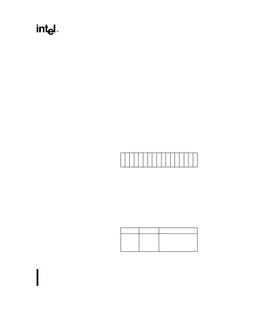
The 16-bit error code is used by the operating sys-
tem to determine how to handle the Page Fault. Fig-
ure 4.13 shows the format of the Page Fault error
code and the interpretation of the bits. Even though
the bits in the error code (U/S, W/R, and P) have
similar names as the bits in the Page Directory/Ta-
ble Entries, the interpretation of the error code bits is
different. Figure 4.14 indicates what type of access
caused the page fault.
15
3 2 1 0
U W
U U U U U U U U U U U U U U D D P
S R
Figure 4.13. Page Fault Error Code Format
U/S
: The U/S bit indicates whether the access
causing the fault occurred when the processor was
executing in User Mode (U/S
e
1) or in Supervisor
mode (U/S
e
0)
W/R
: The W/R bit indicates whether the access
causing the fault was a Read (W/R
e
0) or a Write
(W/R
e
1)
P
: The P bit indicates whether a page fault was
caused by a not-present page (P
e
0), or by a page
level protection violation (P
e
1)
U
e
Undefined
U/S
W/R
Access Type
0
0
1
1
0
1
0
1
Supervisor
*
Read
Supervisor Write
User Read
User Write
*
Descriptor table access will fault with U/S
e
0, even if
the program is executing at level 3.
Figure 4.14. Type of Access Causing Page Fault
35
相關(guān)PDF資料 |
PDF描述 |
|---|---|
| INTEL386 | Intel386 EX Embedded Microprocessor |
| Intel387 dx | DX Math Coprocessor(32位數(shù)學(xué)協(xié)處理器) |
| Intel387 sx | SX Math Coprocessor(32位數(shù)學(xué)協(xié)處理器) |
| INTEL486 GX | Emedded Ultra-Low Power INTEL486 GX Processor(嵌入式超低能量處理器) |
| INTEL486 SX | Emedded Ultra-Low Power INTEL486 SX Processor(嵌入式超低能量處理器) |
相關(guān)代理商/技術(shù)參數(shù) |
參數(shù)描述 |
|---|---|
| INTEL387 | 制造商:INTEL 制造商全稱:Intel Corporation 功能描述:Intel387TM SX MATH COPROCESSOR |
| INTEL387DX | 制造商:未知廠家 制造商全稱:未知廠家 功能描述:Intel387 DX - MATH COPROCESSOR |
| INTEL387SX | 制造商:INTEL 制造商全稱:Intel Corporation 功能描述:Intel387 SX - MATH COPROCESSOR |
| INTEL387TMDX | 制造商:INTEL 制造商全稱:Intel Corporation 功能描述:Intel387TM DX MATH COPROCESSOR |
| INTEL740 | 制造商:未知廠家 制造商全稱:未知廠家 功能描述:64-Bit Graphics (GUI) Accelerator |
發(fā)布緊急采購,3分鐘左右您將得到回復(fù)。