- 您現在的位置:買賣IC網 > PDF目錄377496 > intel386 SX (Intel Corp.) 32-Bit CPU With a 16-Bit External Data Bus And a 24-bit External Address Bus(帶16位內部數據總線和24位內部地址總線32位微處理器) PDF資料下載
參數資料
| 型號: | intel386 SX |
| 廠商: | Intel Corp. |
| 英文描述: | 32-Bit CPU With a 16-Bit External Data Bus And a 24-bit External Address Bus(帶16位內部數據總線和24位內部地址總線32位微處理器) |
| 中文描述: | 32位16位外部數據總線和24位外部地址總線CPU(帶16位內部數據總線和24位內部地址總線32位微處理器) |
| 文件頁數: | 60/102頁 |
| 文件大小: | 1166K |
| 代理商: | INTEL386 SX |
第1頁第2頁第3頁第4頁第5頁第6頁第7頁第8頁第9頁第10頁第11頁第12頁第13頁第14頁第15頁第16頁第17頁第18頁第19頁第20頁第21頁第22頁第23頁第24頁第25頁第26頁第27頁第28頁第29頁第30頁第31頁第32頁第33頁第34頁第35頁第36頁第37頁第38頁第39頁第40頁第41頁第42頁第43頁第44頁第45頁第46頁第47頁第48頁第49頁第50頁第51頁第52頁第53頁第54頁第55頁第56頁第57頁第58頁第59頁當前第60頁第61頁第62頁第63頁第64頁第65頁第66頁第67頁第68頁第69頁第70頁第71頁第72頁第73頁第74頁第75頁第76頁第77頁第78頁第79頁第80頁第81頁第82頁第83頁第84頁第85頁第86頁第87頁第88頁第89頁第90頁第91頁第92頁第93頁第94頁第95頁第96頁第97頁第98頁第99頁第100頁第101頁第102頁
Intel386
TM
SX MICROPROCESSOR
FLOAT
Activating the FLT
Y
input floats all Intel386 SX bidi-
rectional and output signals, including HLDA. Assert-
ing FLT
Y
isolates the Intel386 SX from the sur-
rounding circuitry.
As the Intel386 SX is packaged in a surface mount
PQFP, it cannot be removed from the motherboard
when In-Circuit Emulation (ICE) is needed. The
FLT
Y
input allows the Intel386 SX to be electrically
isolated from the surrounding circuitry. This allows
connection of an emulator to the Intel386 SX PQFP
without removing it from the PCB. This method of
emulation is referred to as ON-Circuit Emulation
(ONCE).
ENTERING AND EXITING FLOAT
FLT
Y
is an asynchronous, active-low input. It is rec-
ognized on the rising edge of CLK2. When recog-
nized, it aborts the current bus cycle and floats the
outputs of the Intel386 SX (Figure 5.20). FLT
Y
must
be held low for a minimum of 16 CLK2 cycles. Reset
should be asserted and held asserted until after
FLT
Y
is deasserted. This will ensure that the
Intel386 SX will exit float in a valid state.
Asserting the FLT
Y
input unconditionally aborts the
current bus cycle and forces the Intel386 SX into the
FLOAT mode. Since activating FLT
Y
unconditional-
ly forces the Intel386 SX into FLOAT mode, the
Intel386 SX is not guaranteed to enter FLOAT in a
valid state. After deactivating FLT
Y
, the Intel386 SX
is not guaranteed to exit FLOAT mode in a valid
state. This is not a problem as the FLT
Y
pin is
meant to be used only during ONCE. After exiting
FLOAT, the Intel386 SX must be reset to return it to
a valid state. Reset should be asserted before FLT
Y
is deasserted. This will ensure that the Intel386 SX
will exit float in a valid state.
FLT
Y
has an internal pull-up resistor, and if it is not
used it should be unconnected.
BUS ACTIVITY DURING AND FOLLOWING
RESET
RESET is the highest priority input signal, capable of
interrupting any processor activity when it is assert-
ed. A bus cycle in progress can be aborted at any
stage, or idle states or bus hold acknowledge states
discontinued so that the reset state is established.
240187–32
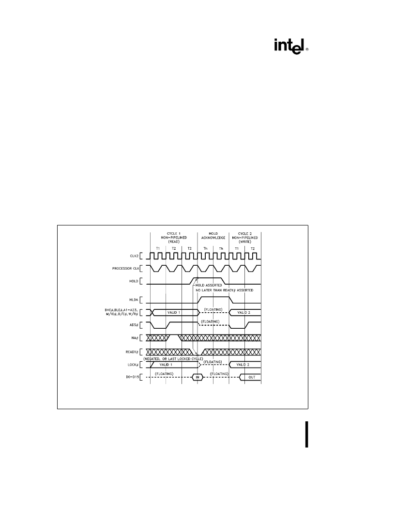
NOTE:
HOLD is a synchronous input and can be asserted at any CLK2 edge, provided setup and hold (t
23
and t
24
) require-
ments are met. This waveform is useful for determining Hold Acknowledge latency.
Figure 5.17. Requesting Hold from Active Bus (NA
Y
inactive)
60
相關PDF資料 |
PDF描述 |
|---|---|
| INTEL386 | Intel386 EX Embedded Microprocessor |
| Intel387 dx | DX Math Coprocessor(32位數學協(xié)處理器) |
| Intel387 sx | SX Math Coprocessor(32位數學協(xié)處理器) |
| INTEL486 GX | Emedded Ultra-Low Power INTEL486 GX Processor(嵌入式超低能量處理器) |
| INTEL486 SX | Emedded Ultra-Low Power INTEL486 SX Processor(嵌入式超低能量處理器) |
相關代理商/技術參數 |
參數描述 |
|---|---|
| INTEL387 | 制造商:INTEL 制造商全稱:Intel Corporation 功能描述:Intel387TM SX MATH COPROCESSOR |
| INTEL387DX | 制造商:未知廠家 制造商全稱:未知廠家 功能描述:Intel387 DX - MATH COPROCESSOR |
| INTEL387SX | 制造商:INTEL 制造商全稱:Intel Corporation 功能描述:Intel387 SX - MATH COPROCESSOR |
| INTEL387TMDX | 制造商:INTEL 制造商全稱:Intel Corporation 功能描述:Intel387TM DX MATH COPROCESSOR |
| INTEL740 | 制造商:未知廠家 制造商全稱:未知廠家 功能描述:64-Bit Graphics (GUI) Accelerator |
發(fā)布緊急采購,3分鐘左右您將得到回復。