- 您現(xiàn)在的位置:買賣IC網(wǎng) > PDF目錄378045 > PCI1410GHK (Texas Instruments, Inc.) PC CARD CONTROLLERS PDF資料下載
參數(shù)資料
| 型號: | PCI1410GHK |
| 廠商: | Texas Instruments, Inc. |
| 英文描述: | PC CARD CONTROLLERS |
| 中文描述: | PC卡控制器 |
| 文件頁數(shù): | 41/145頁 |
| 文件大小: | 606K |
| 代理商: | PCI1410GHK |
第1頁第2頁第3頁第4頁第5頁第6頁第7頁第8頁第9頁第10頁第11頁第12頁第13頁第14頁第15頁第16頁第17頁第18頁第19頁第20頁第21頁第22頁第23頁第24頁第25頁第26頁第27頁第28頁第29頁第30頁第31頁第32頁第33頁第34頁第35頁第36頁第37頁第38頁第39頁第40頁當(dāng)前第41頁第42頁第43頁第44頁第45頁第46頁第47頁第48頁第49頁第50頁第51頁第52頁第53頁第54頁第55頁第56頁第57頁第58頁第59頁第60頁第61頁第62頁第63頁第64頁第65頁第66頁第67頁第68頁第69頁第70頁第71頁第72頁第73頁第74頁第75頁第76頁第77頁第78頁第79頁第80頁第81頁第82頁第83頁第84頁第85頁第86頁第87頁第88頁第89頁第90頁第91頁第92頁第93頁第94頁第95頁第96頁第97頁第98頁第99頁第100頁第101頁第102頁第103頁第104頁第105頁第106頁第107頁第108頁第109頁第110頁第111頁第112頁第113頁第114頁第115頁第116頁第117頁第118頁第119頁第120頁第121頁第122頁第123頁第124頁第125頁第126頁第127頁第128頁第129頁第130頁第131頁第132頁第133頁第134頁第135頁第136頁第137頁第138頁第139頁第140頁第141頁第142頁第143頁第144頁第145頁
3–7
3.5.6
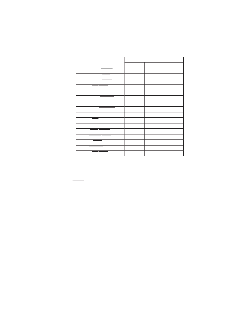
Integrated Pullup Resistors For PC Card Interface
The 1997 PC Card Standardrequires pullup resistors on various terminals to support both CardBus and 16-bit card
configurations. Unlike the PCI1210/1211 which required external pullup resistors, the PCI1410 has integrated all of
these pullup resistors.
SIGNAL NAME
PIN NUMBER
PGE
GGU
GHK
ADDR14/CPERR
C13
104
F14
READY/CINT
D6
132
A10
ADDR15/CIRDY
A12
110
C15
CD1/CCD1
L12
75
L19
VS1/CVS1
C6
131
F11
ADDR19/CBLOCK
D11
103
E19
ADDR20/CSTOP
C12
105
E18
ADDR21/CDEVSEL
B13
107
E17
ADDR22/CTRDY
A13
109
A16
VS2/CVS2
D9
117
E13
RESET/CRST
B9
119
F12
WAIT/CSERR
A5
133
B10
INPACK/CREQ
B8
123
E12
BVD2(SPKR)/CAUDIO
B5
134
C10
BVD1(STSCHG)/CSTSCHG
C5
135
E10
CD2/CCD2
A4
137
A9
3.5.7
SPKROUT and CAUDPWM Usage
SPKROUT carries the digital audio signal from the PC Card to the system. When a 16-bit PC Card is configured for
I/O mode, the BVD2 terminal becomes SPKR. This terminal is also used in CardBus binary audio applications, and
is referred to as CAUDIO. SPKR passes a TTL level digital audio signal to the PCI1410. The CardBus CAUDIO signal
also can pass a single-amplitude binary waveform. The binary audio signal from the PC Card socket is used in the
PCI1410 to produce SPKROUT. This output is enabled by bit 1 (SPKROUTEN) in the card control register (see
Section 4.32).
Older controllers support CAUDIO in binary or PWM mode but use the same terminal (SPKROUT). Some audio chips
may not support both modes on one terminal and may have a separate terminal for binary and PWM. The PCI1410
implementation includes a signal for PWM, CAUDPWM, which can be routed to an MFUNC terminal. Bit 2
(AUD2MUX) located in the card control register is programmed to route a CardBus CAUDIO PWM terminal to
CAUDPWM. See Section 4.30, Multifunction Routing Register for details on configuring the MFUNC terminals.
Figure 3–7 illustrates a sample application using SPKROUT and CAUDPWM.
相關(guān)PDF資料 |
PDF描述 |
|---|---|
| PCI1510GVF | PC CARD CONTROLLERS |
| PCI1510ZVF | PC CARD CONTROLLERS |
| PCI1520I | PC CARD CONTROLLERS |
| PCI4410A | PC CARD AND OHCI CONTROLLER |
| PCI4510PDV | PC CARD AND INTEGRATED 1394A-2000 OHCI TWO PORT PHY/LINK LAYER CONTROLLER |
相關(guān)代理商/技術(shù)參數(shù) |
參數(shù)描述 |
|---|---|
| PCI1410PGE | 功能描述:外圍驅(qū)動器與原件 - PCI PC CARD CONTROLLER RoHS:否 制造商:PLX Technology 工作電源電壓: 最大工作溫度: 安裝風(fēng)格:SMD/SMT 封裝 / 箱體:FCBGA-1156 封裝:Tray |
| PCI1410RFP | 制造商:Rochester Electronics LLC 功能描述:- Bulk |
| PCI1420 | 制造商:TI 制造商全稱:Texas Instruments 功能描述:PC Card Controllers |
| PCI1420EVM | 制造商:Texas Instruments 功能描述:PCI CARD BUS CONTROLLER EVM KIT - Bulk |
| PCI1420GHK | 功能描述:外圍驅(qū)動器與原件 - PCI PC CARD CONTROLLER RoHS:否 制造商:PLX Technology 工作電源電壓: 最大工作溫度: 安裝風(fēng)格:SMD/SMT 封裝 / 箱體:FCBGA-1156 封裝:Tray |
發(fā)布緊急采購,3分鐘左右您將得到回復(fù)。