- 您現(xiàn)在的位置:買賣IC網(wǎng) > PDF目錄378045 > PCI1410GHK (Texas Instruments, Inc.) PC CARD CONTROLLERS PDF資料下載
參數(shù)資料
| 型號: | PCI1410GHK |
| 廠商: | Texas Instruments, Inc. |
| 英文描述: | PC CARD CONTROLLERS |
| 中文描述: | PC卡控制器 |
| 文件頁數(shù): | 56/145頁 |
| 文件大小: | 606K |
| 代理商: | PCI1410GHK |
第1頁第2頁第3頁第4頁第5頁第6頁第7頁第8頁第9頁第10頁第11頁第12頁第13頁第14頁第15頁第16頁第17頁第18頁第19頁第20頁第21頁第22頁第23頁第24頁第25頁第26頁第27頁第28頁第29頁第30頁第31頁第32頁第33頁第34頁第35頁第36頁第37頁第38頁第39頁第40頁第41頁第42頁第43頁第44頁第45頁第46頁第47頁第48頁第49頁第50頁第51頁第52頁第53頁第54頁第55頁當(dāng)前第56頁第57頁第58頁第59頁第60頁第61頁第62頁第63頁第64頁第65頁第66頁第67頁第68頁第69頁第70頁第71頁第72頁第73頁第74頁第75頁第76頁第77頁第78頁第79頁第80頁第81頁第82頁第83頁第84頁第85頁第86頁第87頁第88頁第89頁第90頁第91頁第92頁第93頁第94頁第95頁第96頁第97頁第98頁第99頁第100頁第101頁第102頁第103頁第104頁第105頁第106頁第107頁第108頁第109頁第110頁第111頁第112頁第113頁第114頁第115頁第116頁第117頁第118頁第119頁第120頁第121頁第122頁第123頁第124頁第125頁第126頁第127頁第128頁第129頁第130頁第131頁第132頁第133頁第134頁第135頁第136頁第137頁第138頁第139頁第140頁第141頁第142頁第143頁第144頁第145頁
3–22
Card
I/F
PC Card
Socket
CSTSMASK
RIENB
RI_OUT
RI_OUT Function
RINGEN
CDRESUME
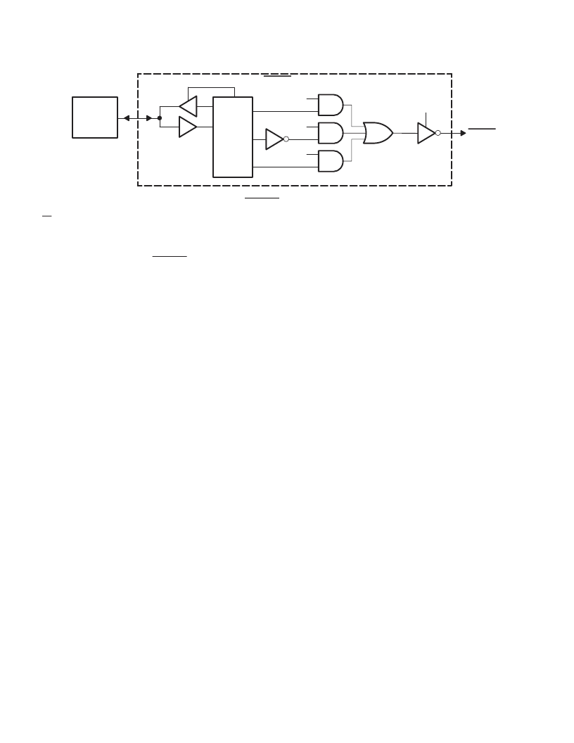
Figure 3–19. RI_OUT Functional Diagram
RI from the 16-bit PC Card interface is masked by bit 7 (RINGEN) in the ExCA interrupt and general control register
(ExCA offset 03h, see Section 5.4). This is programmed on a per-socket basis and is only applicable when a 16-bit
card is powered in the socket.
The CBWAKE signaling to RI_OUT is enabled through the same mask as the CSC event for CSTSCHG. The mask
bit (bit 0, CSTSMASK) is programmed through the socket mask register (CardBus offset 04h, see Section 6.2) in the
CardBus socket registers.
3.8.7
PCI Power Management
The PCI Bus Power Management Interface Specification for PCI to CardBus Bridgesestablishes the infrastructure
required to let the operating system control the power of PCI functions. This is done by defining a standard PCI
interface and operations to manage the power of PCI functions on the bus. The PCI bus and the PCI functions can
be assigned one of four software-visible power management states that result in varying levels of power savings.
The four power management states of PCI functions are:
D0 – Fully-on state
D1 and D2 – Intermediate states
D3 – Off state
Similarly, bus power states of the PCI bus are B0–B3. The bus power states B0–B3 are derived from the device power
state of the originating bridge device.
For the operating system (OS) to power manage the device power states on the PCI bus, the PCI function should
support four power management operations. These operations are:
Capabilities reporting
Power status reporting
Setting the power state
System wake up
The OS identifies the capabilities of the PCI function by traversing the new capabilities list. The presence of
capabilities in addition to the standard PCI capabilities is indicated by a 1 in bit 4 (CAPLIST) of the status register
(offset 06h, see Section 4.5).
The capabilities pointer provides access to the first item in the linked list of capabilities. For the PCI1410, a CardBus
bridge with PCI configuration space header type 2, the capabilities pointer is mapped to an offset of 14h. The first
byte of each capability register block is required to be a unique ID of that capability. PCI power management has been
assigned an ID of 01h. The next byte is a pointer to the next pointer item in the list of capabilities. If there are no more
items in the list, then the next item pointer should be set to 0. The registers following the next item pointer are specific
to the capabilities of their corresponding power management functions. The PCI power management capability
implements the register block outlined in Table 3–11.
相關(guān)PDF資料 |
PDF描述 |
|---|---|
| PCI1510GVF | PC CARD CONTROLLERS |
| PCI1510ZVF | PC CARD CONTROLLERS |
| PCI1520I | PC CARD CONTROLLERS |
| PCI4410A | PC CARD AND OHCI CONTROLLER |
| PCI4510PDV | PC CARD AND INTEGRATED 1394A-2000 OHCI TWO PORT PHY/LINK LAYER CONTROLLER |
相關(guān)代理商/技術(shù)參數(shù) |
參數(shù)描述 |
|---|---|
| PCI1410PGE | 功能描述:外圍驅(qū)動器與原件 - PCI PC CARD CONTROLLER RoHS:否 制造商:PLX Technology 工作電源電壓: 最大工作溫度: 安裝風(fēng)格:SMD/SMT 封裝 / 箱體:FCBGA-1156 封裝:Tray |
| PCI1410RFP | 制造商:Rochester Electronics LLC 功能描述:- Bulk |
| PCI1420 | 制造商:TI 制造商全稱:Texas Instruments 功能描述:PC Card Controllers |
| PCI1420EVM | 制造商:Texas Instruments 功能描述:PCI CARD BUS CONTROLLER EVM KIT - Bulk |
| PCI1420GHK | 功能描述:外圍驅(qū)動器與原件 - PCI PC CARD CONTROLLER RoHS:否 制造商:PLX Technology 工作電源電壓: 最大工作溫度: 安裝風(fēng)格:SMD/SMT 封裝 / 箱體:FCBGA-1156 封裝:Tray |
發(fā)布緊急采購,3分鐘左右您將得到回復(fù)。