- 您現(xiàn)在的位置:買賣IC網(wǎng) > PDF目錄378045 > PCI1410GHK (Texas Instruments, Inc.) PC CARD CONTROLLERS PDF資料下載
參數(shù)資料
| 型號(hào): | PCI1410GHK |
| 廠商: | Texas Instruments, Inc. |
| 英文描述: | PC CARD CONTROLLERS |
| 中文描述: | PC卡控制器 |
| 文件頁(yè)數(shù): | 42/145頁(yè) |
| 文件大?。?/td> | 606K |
| 代理商: | PCI1410GHK |
第1頁(yè)第2頁(yè)第3頁(yè)第4頁(yè)第5頁(yè)第6頁(yè)第7頁(yè)第8頁(yè)第9頁(yè)第10頁(yè)第11頁(yè)第12頁(yè)第13頁(yè)第14頁(yè)第15頁(yè)第16頁(yè)第17頁(yè)第18頁(yè)第19頁(yè)第20頁(yè)第21頁(yè)第22頁(yè)第23頁(yè)第24頁(yè)第25頁(yè)第26頁(yè)第27頁(yè)第28頁(yè)第29頁(yè)第30頁(yè)第31頁(yè)第32頁(yè)第33頁(yè)第34頁(yè)第35頁(yè)第36頁(yè)第37頁(yè)第38頁(yè)第39頁(yè)第40頁(yè)第41頁(yè)當(dāng)前第42頁(yè)第43頁(yè)第44頁(yè)第45頁(yè)第46頁(yè)第47頁(yè)第48頁(yè)第49頁(yè)第50頁(yè)第51頁(yè)第52頁(yè)第53頁(yè)第54頁(yè)第55頁(yè)第56頁(yè)第57頁(yè)第58頁(yè)第59頁(yè)第60頁(yè)第61頁(yè)第62頁(yè)第63頁(yè)第64頁(yè)第65頁(yè)第66頁(yè)第67頁(yè)第68頁(yè)第69頁(yè)第70頁(yè)第71頁(yè)第72頁(yè)第73頁(yè)第74頁(yè)第75頁(yè)第76頁(yè)第77頁(yè)第78頁(yè)第79頁(yè)第80頁(yè)第81頁(yè)第82頁(yè)第83頁(yè)第84頁(yè)第85頁(yè)第86頁(yè)第87頁(yè)第88頁(yè)第89頁(yè)第90頁(yè)第91頁(yè)第92頁(yè)第93頁(yè)第94頁(yè)第95頁(yè)第96頁(yè)第97頁(yè)第98頁(yè)第99頁(yè)第100頁(yè)第101頁(yè)第102頁(yè)第103頁(yè)第104頁(yè)第105頁(yè)第106頁(yè)第107頁(yè)第108頁(yè)第109頁(yè)第110頁(yè)第111頁(yè)第112頁(yè)第113頁(yè)第114頁(yè)第115頁(yè)第116頁(yè)第117頁(yè)第118頁(yè)第119頁(yè)第120頁(yè)第121頁(yè)第122頁(yè)第123頁(yè)第124頁(yè)第125頁(yè)第126頁(yè)第127頁(yè)第128頁(yè)第129頁(yè)第130頁(yè)第131頁(yè)第132頁(yè)第133頁(yè)第134頁(yè)第135頁(yè)第136頁(yè)第137頁(yè)第138頁(yè)第139頁(yè)第140頁(yè)第141頁(yè)第142頁(yè)第143頁(yè)第144頁(yè)第145頁(yè)
3–8
Speaker
Subsystem
BINARY_SPKR
System
Core Logic
PCI1410
CAUDPWM
SPKROUT
PWM_SPKR
Figure 3–7. Sample Application of SPKROUT and CAUDPWM
3.5.8
LED Socket Activity Indicators
The socket activity LEDs are provided to indicate when a PC Card is being accessed. The LED_SKT signal can be
routed to the multifunction terminals. When configured for LED output, this terminal outputs an active high signal to
indicate socket activity. See Section 4.30, Multifunction Routing Register
for details on configuring the multifunction
terminals.
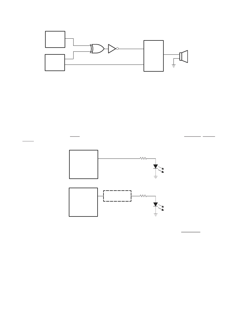
The LED signal is active high and is driven in pulses of 64-ms duration. When the LED is not being driven high, it is
driven to a low state. Either of the two circuits shown in Figure 3–8 can be implemented to provide LED signaling and
it is left for the board designer to implement the circuit that best fits the application.
The LED activity signals are valid when a card is inserted, powered, and not in reset. For PC Card-16, the LED activity
signal is pulsed when READY/IREQ is low. For CardBus cards, the LED activity signal is pulsed if CFRAME, CIRDY,
or CREQ is active.
PCI1410
Specific Delay
Current Limiting
R
≈
500
PCI1410
Current Limiting
R
≈
500
LED
LED
Figure 3–8. Two Sample LED Circuits
As indicated, the LED signals are driven for a period of 64 ms by a counter circuit. To avoid the possibility of the LED
appearing to be stuck when the PCI clock is stopped, the LED signaling is cut off when the SUSPEND signal is
asserted, when the PCI clock is to be stopped during the clock run protocol, or when in the D2 or D1 power state.
If any additional socket activity occurs during this counter cycle, then the counter is reset and the LED signal remains
driven. If socket activity is frequent (at least once every 64 ms), then the LED signal remains driven.
3.5.9
PC Card-16 Distributed DMA Support
The PCI1410 supports a distributed DMA slave engine for 16-bit PC Card DMA support. The distributed DMA (DDMA)
slave register set provides the programmability necessary for the slave DDMA engine. Table 3–2 provides the DDMA
register configuration.
相關(guān)PDF資料 |
PDF描述 |
|---|---|
| PCI1510GVF | PC CARD CONTROLLERS |
| PCI1510ZVF | PC CARD CONTROLLERS |
| PCI1520I | PC CARD CONTROLLERS |
| PCI4410A | PC CARD AND OHCI CONTROLLER |
| PCI4510PDV | PC CARD AND INTEGRATED 1394A-2000 OHCI TWO PORT PHY/LINK LAYER CONTROLLER |
相關(guān)代理商/技術(shù)參數(shù) |
參數(shù)描述 |
|---|---|
| PCI1410PGE | 功能描述:外圍驅(qū)動(dòng)器與原件 - PCI PC CARD CONTROLLER RoHS:否 制造商:PLX Technology 工作電源電壓: 最大工作溫度: 安裝風(fēng)格:SMD/SMT 封裝 / 箱體:FCBGA-1156 封裝:Tray |
| PCI1410RFP | 制造商:Rochester Electronics LLC 功能描述:- Bulk |
| PCI1420 | 制造商:TI 制造商全稱:Texas Instruments 功能描述:PC Card Controllers |
| PCI1420EVM | 制造商:Texas Instruments 功能描述:PCI CARD BUS CONTROLLER EVM KIT - Bulk |
| PCI1420GHK | 功能描述:外圍驅(qū)動(dòng)器與原件 - PCI PC CARD CONTROLLER RoHS:否 制造商:PLX Technology 工作電源電壓: 最大工作溫度: 安裝風(fēng)格:SMD/SMT 封裝 / 箱體:FCBGA-1156 封裝:Tray |
發(fā)布緊急采購(gòu),3分鐘左右您將得到回復(fù)。