- 您現(xiàn)在的位置:買賣IC網(wǎng) > PDF目錄25648 > STM32W108HBU7 (STMICROELECTRONICS) SPECIALTY MICROPROCESSOR CIRCUIT, QCC40 PDF資料下載
參數(shù)資料
| 型號(hào): | STM32W108HBU7 |
| 廠商: | STMICROELECTRONICS |
| 元件分類: | 微控制器/微處理器 |
| 英文描述: | SPECIALTY MICROPROCESSOR CIRCUIT, QCC40 |
| 封裝: | 6 X 6 MM, 0.50 MM PITCH, ROHS COMPLIANT, VFQFPN-40 |
| 文件頁數(shù): | 16/198頁 |
| 文件大?。?/td> | 2871K |
| 代理商: | STM32W108HBU7 |
第1頁第2頁第3頁第4頁第5頁第6頁第7頁第8頁第9頁第10頁第11頁第12頁第13頁第14頁第15頁當(dāng)前第16頁第17頁第18頁第19頁第20頁第21頁第22頁第23頁第24頁第25頁第26頁第27頁第28頁第29頁第30頁第31頁第32頁第33頁第34頁第35頁第36頁第37頁第38頁第39頁第40頁第41頁第42頁第43頁第44頁第45頁第46頁第47頁第48頁第49頁第50頁第51頁第52頁第53頁第54頁第55頁第56頁第57頁第58頁第59頁第60頁第61頁第62頁第63頁第64頁第65頁第66頁第67頁第68頁第69頁第70頁第71頁第72頁第73頁第74頁第75頁第76頁第77頁第78頁第79頁第80頁第81頁第82頁第83頁第84頁第85頁第86頁第87頁第88頁第89頁第90頁第91頁第92頁第93頁第94頁第95頁第96頁第97頁第98頁第99頁第100頁第101頁第102頁第103頁第104頁第105頁第106頁第107頁第108頁第109頁第110頁第111頁第112頁第113頁第114頁第115頁第116頁第117頁第118頁第119頁第120頁第121頁第122頁第123頁第124頁第125頁第126頁第127頁第128頁第129頁第130頁第131頁第132頁第133頁第134頁第135頁第136頁第137頁第138頁第139頁第140頁第141頁第142頁第143頁第144頁第145頁第146頁第147頁第148頁第149頁第150頁第151頁第152頁第153頁第154頁第155頁第156頁第157頁第158頁第159頁第160頁第161頁第162頁第163頁第164頁第165頁第166頁第167頁第168頁第169頁第170頁第171頁第172頁第173頁第174頁第175頁第176頁第177頁第178頁第179頁第180頁第181頁第182頁第183頁第184頁第185頁第186頁第187頁第188頁第189頁第190頁第191頁第192頁第193頁第194頁第195頁第196頁第197頁第198頁

General-purpose timers
STM32W108CB, STM32W108HB
112/198
Doc ID 16252 Rev 3
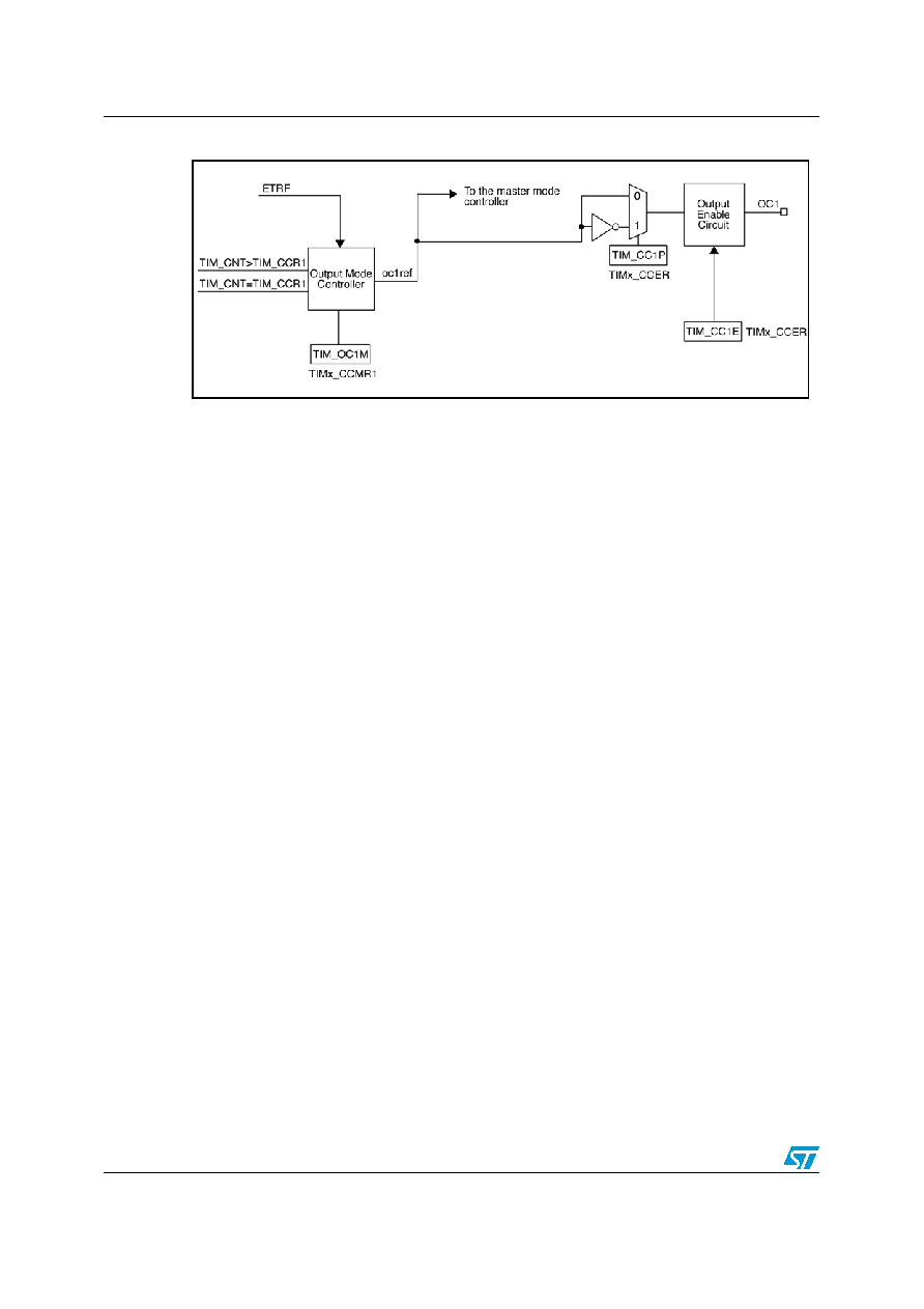
Figure 32.
Output stage of capture/compare channel (channel 1)
The capture/compare block is made of a buffer register and a shadow register. Writes and
reads always access the buffer register.
In capture mode, captures are first written to the shadow register, then copied into the buffer
register.
In compare mode, the content of the buffer register is copied into the shadow register which
is compared to the counter.
10.1.5
Input capture mode
In input capture mode, a capture/compare register (TIMx_CCRy) latches the value of the
counter after a transition is detected by the corresponding ICy signal. When a capture
occurs, the corresponding INT_TIMCCyIF flag in the INT_TIMxFLAG register is set, and an
interrupt request is sent if enabled.
If a capture occurs when the INT_TIMCCyIF flag is already high, then the missed capture
flag INT_TIMMISSCCyIF in the INT_TIMxMISS register is set. INT_TIMCCyIF can be
cleared by software writing a 1 to its bit or reading the captured data stored in the
TIMx_CCRy register. To clear the INT_TIMMISSCCyIF bit, write a 1 to it.
The following example shows how to capture the counter value in the TIMx_CCR1 when the
TI1 input rises.
●
Select the active input: TIMx_CCR1 must be linked to the TI1 input, so write the
TIM_CC1S bits to 01 in the TIMx_CCMR1 register. As soon as TIM_CC1S becomes
different from 00, the channel is configured in input and the TIMx_CCR1 register
becomes read-only.
●
Program the required input filter duration with respect to the signal connected to the
timer, when the input is one of the TIy (ICyF bits in the TIMx_CCMR1 register).
Consider a situation in which, when toggling, the input signal is unstable during at most
5 internal clock cycles. The filter duration must be longer than these 5 clock cycles. The
transition on TI1 can be validated when 8 consecutive samples with the new level have
been detected (sampled at PCLK frequency). To do this, write the TIM_IC1F bits to
0011 in the TIMx_CCMR1 register.
●
Select the edge of the active transition on the TI1 channel by writing the TIM_CC1P bit
to 0 in the TIMx_CCER register (rising edge in this case).
●
Program the input prescaler: In this example, the capture is to be performed at each
valid transition, so the prescaler is disabled (write the TIM_IC1PS bits to 00 in the
TIMx_CCMR1 register).
相關(guān)PDF資料 |
PDF描述 |
|---|---|
| STP506C-2IW-012V | SINGLE COLOR DISPLAY CLUSTER, WHITE, 152.4 mm |
| SUGR47M | DUAL COLOR LED, RED/GREEN, 5 mm |
| SUR76D | SINGLE COLOR LED, RED, 3 mm |
| SUY17D | SINGLE COLOR LED, YELLOW, 3.9 mm |
| SY405T | SINGLE COLOR LED, AMBER, 2.7 mm |
相關(guān)代理商/技術(shù)參數(shù) |
參數(shù)描述 |
|---|---|
| STM32WC-RFCKIT | 功能描述:Zigbee/802.15.4開發(fā)工具 STM32W Low-Cost RF STM32F103 MCU Kit RoHS:否 制造商:Silicon Labs 產(chǎn)品:Development Kits 工具用于評(píng)估:EM35x 頻率:2.4 GHz 接口類型:USB 工作電源電壓: |
| STM32W-RFCKIT | 功能描述:開發(fā)板和工具包 - 無線 STM32W RF CNTRL KIT STM32F103 USB JTAG RoHS:否 制造商:Arduino 產(chǎn)品:Evaluation Boards 工具用于評(píng)估:AT32UC3L 核心:AVR32 頻率: 接口類型:USB 工作電源電壓:5 V |
| STM3-3 | 制造商:RINO MECH.(GENGARELL 功能描述: |
| STM330 | 制造商:EnOcean GmbH 功能描述:Temperature energy harvester, 868MHz |
| STM330U | 制造商:EnOcean GmbH 功能描述:Temperature energy harvester, 315MHz 制造商:EnOcean GmbH 功能描述:Temperature energy harvester, 902MHz |
發(fā)布緊急采購,3分鐘左右您將得到回復(fù)。