- 您現(xiàn)在的位置:買賣IC網(wǎng) > PDF目錄371179 > T7121-EL2 T7121 HDLC Interface for ISDN PDF資料下載
參數(shù)資料
| 型號: | T7121-EL2 |
| 英文描述: | T7121 HDLC Interface for ISDN |
| 中文描述: | T7121的HDLC接口用于ISDN |
| 文件頁數(shù): | 19/68頁 |
| 文件大小: | 685K |
| 代理商: | T7121-EL2 |
第1頁第2頁第3頁第4頁第5頁第6頁第7頁第8頁第9頁第10頁第11頁第12頁第13頁第14頁第15頁第16頁第17頁第18頁當(dāng)前第19頁第20頁第21頁第22頁第23頁第24頁第25頁第26頁第27頁第28頁第29頁第30頁第31頁第32頁第33頁第34頁第35頁第36頁第37頁第38頁第39頁第40頁第41頁第42頁第43頁第44頁第45頁第46頁第47頁第48頁第49頁第50頁第51頁第52頁第53頁第54頁第55頁第56頁第57頁第58頁第59頁第60頁第61頁第62頁第63頁第64頁第65頁第66頁第67頁第68頁
Lucent Technologies Inc.
19
Data Sheet
April 1997
T7121 HDLC Interface for ISDN (HIFI-64)
Functional Description
(continued)
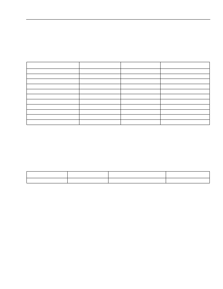
SLD and IOM2 Examples
Example register settings for configuring to SLD, IOM2, or K2 TDM highways are shown below. These settings
assume HWYEN (R0—B7) = 1 and FSPOL (R0—B6) = 1.
HDLC Operation
This section describes the standard HDLC functions performed by the HIFI-64. HDLC operation is the default
mode of operation. The transmitter accepts parallel data from the transmit FIFO, converts it to a serial bit stream,
provides bit stuffing as necessary, adds the CRC and the opening and closing flags, and sends the framed serial
bit stream on the selected transmit data pin(s). The receiver accepts serial data on the selected receive data pin,
identifies frames for proper format, reconstructs data bytes, provides bit destuffing as necessary, and loads parallel
data in the receive FIFO. HDLC frames on the serial link have the following format:
All bits between the opening flag and the CRC are considered user data bits. User data bits such as the address,
control, and information fields for LAPB or LAPD frames are fetched from the transmit FIFO for transmission.
Received user data bits are stored in the FIFO buffers. The 16 bits preceding the closing flag are the frame check
sequence or cyclic redundancy check (CRC) bits.
Zero-Bit Insertion/Deletion (Bit Stuffing/Destuffing)
The HDLC protocol recognizes three special bit patterns: flags, aborts, and idles. These patterns have the com-
mon characteristic of containing at least six consecutive 1s. A user data byte can contain one of these special pat-
terns. Transmitter zero-bit stuffing is done on user data and CRC fields of the frame to avoid transmitting one of
these special patterns. Whenever five 1s occur between flags, a 0 bit is automatically inserted after the fifth 1, prior
to transmission of the next bit. On the receive side, if five successive 1s are detected followed by a 0, the 0 is
assumed to have been inserted and is deleted (bit destuffing).
Table 4. Example Register Settings
Register
IOM2/GCI
0
1
1
1
111
(# of time slots) – 1
Desired time slot
0
111
(# of time slots) – 1
Desired time slot
SLD
0
1
0
1
111
000011
K2
0
1
0
1
111
FE, (R0—B5)
P21CTL, (R5—B6)
CMS, (R8—B6)
CLKXI, (R9—B4)
TBOF[2—0], (R9—B[7—5])
TTSOF[5 0], (R10—B[5—0])
TSLT[5—0], (R7—B[5—0])
CLKRI, (R9—B0)
RBOF[2—0], (R9—B[3—1])
RTSOF[5—0], (R11—B[5—0])
RSLT[5—0], (R8—B[5—0])
000000, 000111
000001—000111, 000000
0
111
000000, 000111
000001—000111, 000000
000000—000011
0
111
000011
000100—000111
Opening Flag
01111110
User Data Field
≥
8 bits
Frame Check Sequence (CRC)
16 bits
Closing Flag
01111110
相關(guān)PDF資料 |
PDF描述 |
|---|---|
| T7121-PL2 | T7121 HDLC Interface for ISDN |
| T7121 | HDLC Interface for ISDN (HIFI-64)(應(yīng)用于ISDN的HDLC(高階數(shù)據(jù)鏈路)接口) |
| T7502 | T7502 Dual PCM Codec with Filters |
| T7503 | T7503 Dual PCM Codec with Filters |
| T7504 | T7504 and T75504 Quad PCM Codecs with Filters |
相關(guān)代理商/技術(shù)參數(shù) |
參數(shù)描述 |
|---|---|
| T7-121F1 | 功能描述:撥動開關(guān) ON OFF ON 1 Pole Standard Bat Handle RoHS:否 制造商:OTTO 觸點形式: 開關(guān)功能: 電流額定值: 電壓額定值 AC: 電壓額定值 DC: 功率額定值: 端接類型: 安裝風(fēng)格: 端子密封: 觸點電鍍: 照明: |
| T7-121F5 | 功能描述:撥動開關(guān) ON OFF ON 1 Pole Standard Bat Handle RoHS:否 制造商:OTTO 觸點形式: 開關(guān)功能: 電流額定值: 電壓額定值 AC: 電壓額定值 DC: 功率額定值: 端接類型: 安裝風(fēng)格: 端子密封: 觸點電鍍: 照明: |
| T7-121G1 | 功能描述:撥動開關(guān) (ON) OFF ON 1 Pole Standard Bat Handle RoHS:否 制造商:OTTO 觸點形式: 開關(guān)功能: 電流額定值: 電壓額定值 AC: 電壓額定值 DC: 功率額定值: 端接類型: 安裝風(fēng)格: 端子密封: 觸點電鍍: 照明: |
| T7-121G5 | 功能描述:撥動開關(guān) (ON) OFF ON 1 Pole Standard Bat Handle RoHS:否 制造商:OTTO 觸點形式: 開關(guān)功能: 電流額定值: 電壓額定值 AC: 電壓額定值 DC: 功率額定值: 端接類型: 安裝風(fēng)格: 端子密封: 觸點電鍍: 照明: |
| T7-121H1 | 制造商:OTTO 功能描述:Toggle Switches OFF NONE ON 1 Pole Standard Bat Handle 制造商:OTTO Engineering Inc 功能描述:TOGGLE SWITCH 1 POLE |
發(fā)布緊急采購,3分鐘左右您將得到回復(fù)。