- 您現(xiàn)在的位置:買賣IC網(wǎng) > PDF目錄371374 > 22363A Simple System Interface for UltraNAND Flash PDF資料下載
參數(shù)資料
| 型號: | 22363A |
| 英文描述: | Simple System Interface for UltraNAND Flash |
| 中文描述: | 簡單的系統(tǒng)接口UltraNAND閃光 |
| 文件頁數(shù): | 3/21頁 |
| 文件大小: | 725K |
| 代理商: | 22363A |

2
Simple System Interface for UltraNAND Flash
is included in this application note. The PLDs gener-
ated are shown in Figure 4 and Figure 5.
System Interface Description
Using Programmable I/O
In many applications using UltraNAND, there may be
programmable I/O lines available, either in a micro-
controller or the system interface logic, that can be
used to generate the UltraNAND CE#, CLE, ALE, SE#,
and WP# inputs. With enough programmable I/O lines
available, the Interface PLD described in this applica-
tion note is not required, and the system can provide all
of the interface support needed through those pro-
grammable I/O lines. If WP# does not need to be dy-
namically controlled by the system, only four
programmable I/O lines are required. This application
note is intended to describe the basic logic needed to
control up to three UltraNAND banks for those applica-
tions that do not have programmable I/O lines avail-
able.
Typical System Implementation
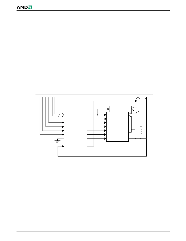
A typical application of the simple system interface is
shown in Figure 1 with the Interface PLD supporting a
single UltraNAND bank consisting of two UltraNAND
devices. The Interface PLD uses the usual system
control signals to create the full set of control signals
needed by the UltraNAND Flash. The system software
is then able to program the Interface PLD to generate
the signal sequence required for proper operation. Be-
cause fewer than three UltraNAND banks are required,
the 16V8 PLD version that supports only one bank was
used.
The INIT signal is unused in this application example.
Refer to the “Boot Loader for UltraNAND Flash Simple
System Interface” application note for information on
generating an INIT signal using a Boot Loader PLD.
Figure 1.
Typical System Interface Application for a Single UltraNAND Bank
System Address, Control, and Data Buses
A[0..3]
WRITE#
READ#
RESET
CE#
OUTCE#
CLE
ALE
WE#
RE#
SE#
WP#
READY
INIT
RY/BY#
4
AmPALLV16V8-10SC
I/O[0..7]
CE#
UltraNAND
I/O[0..7]
CE#
CLE
ALE
WE#
RE#
SE#
WP#
RY/BY#
D6
16
V
CC
Interface PLD
D[8..15]
D[0..7]
相關(guān)PDF資料 |
PDF描述 |
|---|---|
| 22368 | Home Networking Board Design Using PCnet-Home Devices? - (PDF) |
| 22374A | Migrating between Boot and Uniform Sectored Flash Devices |
| 223878119764 | CAPACITOR 1.2UF 16V |
| 223878119766 | CAPACITOR 1.8UF 16V |
| 224-1286-00-0602J | IC SOCKET ZIF 24 WAY |
相關(guān)代理商/技術(shù)參數(shù) |
參數(shù)描述 |
|---|---|
| 223642 | 制造商:ERNI Electronics 功能描述:NP |
| 223650 | 制造商:ERNI Electronics 功能描述: |
| 223650-1 | 制造商:TE Connectivity 功能描述:CONN BP RCP 24 POS 2MM PRESS FIT ST TH - Rail/Tube 制造商:TE Connectivity 功能描述:2mm Centerline Futurebus+ Connectors |
| 223650-2 | 制造商:TE Connectivity 功能描述:Conn Backplane RCP 48 POS 2mm Press Fit ST Thru-Hole |
| 223650-3 | 制造商:TE Connectivity 功能描述:CONN BP 72 POS 2MM ST - Bulk |
發(fā)布緊急采購,3分鐘左右您將得到回復(fù)。