- 您現(xiàn)在的位置:買賣IC網(wǎng) > PDF目錄371374 > 22363A Simple System Interface for UltraNAND Flash PDF資料下載
參數(shù)資料
| 型號(hào): | 22363A |
| 英文描述: | Simple System Interface for UltraNAND Flash |
| 中文描述: | 簡(jiǎn)單的系統(tǒng)接口UltraNAND閃光 |
| 文件頁(yè)數(shù): | 4/21頁(yè) |
| 文件大?。?/td> | 725K |
| 代理商: | 22363A |
第1頁(yè)第2頁(yè)第3頁(yè)當(dāng)前第4頁(yè)第5頁(yè)第6頁(yè)第7頁(yè)第8頁(yè)第9頁(yè)第10頁(yè)第11頁(yè)第12頁(yè)第13頁(yè)第14頁(yè)第15頁(yè)第16頁(yè)第17頁(yè)第18頁(yè)第19頁(yè)第20頁(yè)第21頁(yè)

Simple System Interface for UltraNAND Flash
3
System Interface Signal Description
The UltraNAND Interface PLD is responsible for gener-
ating the signals required by the UltraNAND device,
which are not found in typical systems. These are CLE,
ALE, WE#, RE#, SE#, and WP#. In order to control the
Interface PLD, the system is responsible for providing
some of the more typical address and control signals.
The definition of all pertinent signals, and the source
required to generate the signals, are included in Table
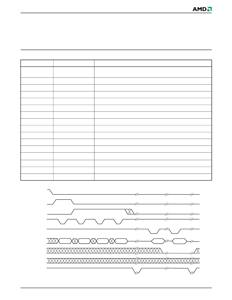
1. A timing diagram of a Read First Half Page opera-
tion is shown in Figure 2, and includes all of the signals
required by UltraNAND.
Table 1.
UltraNAND System Interface Signal Description
Figure 2.
UltraNAND Read First Half Page Timing Diagram
Signal
Source
Definition
INIT
Optional Boot Loader
PLD
From optional “Boot Loader for Simple System Interface” PLD to indicate that
the Boot Loader PLD is initializing UltraNAND
ALE
Interface PLD
Address Latch Enable required for address latch cycles
CLE
Interface PLD
Command Latch Enable required to latch the command
OUTCE[0..2]#
Interface PLD
The Chip Enables used to select the UltraNAND bank(s)
RE#
Interface PLD
Read signal used by UltraNAND for all read cycles
READY
Interface PLD
Tri-state output to allow the system to read the state of the RY/BY# pin(s)
SE#
Interface PLD
Spare Area Enable to control access to the UltraNAND spare area
WE#
Interface PLD
Write signal used by UltraNAND for all write cycles
WP#
Interface PLD
Write Protect to prevent program/erase operations in UltraNAND
A[0..3]
System
Address bus used to select one of sixteen Interface PLD control ports
CE#
System
The Chip Enable used to select the UltraNAND and Interface PLD
I/O[0..7]
System/UltraNAND
The eight I/O lines used to transfer commands, addresses, and data
RESET
System
A system reset signal which remains high until V
CC
is valid
READ#
System
Read signal used by the system for all read cycles
WRITE#
System
Write signal used by the system for all write cycles
RY/BY#
UltraNAND
Ready/Busy signal to indicate the current state of UltraNAND
OUTCE#
RY/BY#
WP#
SE#
I/O[0..7]
RE#
WE#
ALE
CLE
00h
A0-A7
A9-A16
A17-A24
Dout N
Dout 527
相關(guān)PDF資料 |
PDF描述 |
|---|---|
| 22368 | Home Networking Board Design Using PCnet-Home Devices? - (PDF) |
| 22374A | Migrating between Boot and Uniform Sectored Flash Devices |
| 223878119764 | CAPACITOR 1.2UF 16V |
| 223878119766 | CAPACITOR 1.8UF 16V |
| 224-1286-00-0602J | IC SOCKET ZIF 24 WAY |
相關(guān)代理商/技術(shù)參數(shù) |
參數(shù)描述 |
|---|---|
| 223642 | 制造商:ERNI Electronics 功能描述:NP |
| 223650 | 制造商:ERNI Electronics 功能描述: |
| 223650-1 | 制造商:TE Connectivity 功能描述:CONN BP RCP 24 POS 2MM PRESS FIT ST TH - Rail/Tube 制造商:TE Connectivity 功能描述:2mm Centerline Futurebus+ Connectors |
| 223650-2 | 制造商:TE Connectivity 功能描述:Conn Backplane RCP 48 POS 2mm Press Fit ST Thru-Hole |
| 223650-3 | 制造商:TE Connectivity 功能描述:CONN BP 72 POS 2MM ST - Bulk |
發(fā)布緊急采購(gòu),3分鐘左右您將得到回復(fù)。